78 N9912A FieldFox User’s Guide
Field Strength Measurements
Trace 1 - Corrected trace with antenna factor. (Antenna = ON, Apply Corr = ON)
Trace 2 - (View) Uncorrected trace (Apply Corr = OFF)
Trace 4 - (View) Current correction factors are automatically stored in Trace 4.
To see the combined Antenna and Cable correction curve, set Trace 4 to View
state (learn how on page 89) with ALL relevant corrections set to ON.
Learn how to set Y-Axis Units on page 74.
Use a Band Power marker to measure total power over a range of frequencies.
Learn how on page 145.
How to select correction for Field Strength measurements
The Antenna and Cable correction data survives a Mode Preset and Preset.
All Correction ON/OFF states survive a Mode Preset, but NOT a Preset.
Press Scale/Amptd.
Then More
Then Corrections
Then choose from the following:
o Apply Corrections ON OFF Turn ON and OFF correction for all settings
o Antenna ON OFF Turn ON and OFF Antenna correction.
o Edit/Save/Recall Antennas Recall or edit an Antenna Correction table. See
below.
o Cable ON OFF Turn ON and OFF Cable correction.
Edit/Save/Recall Cables Recall or edit a Cable Correction table. See below.
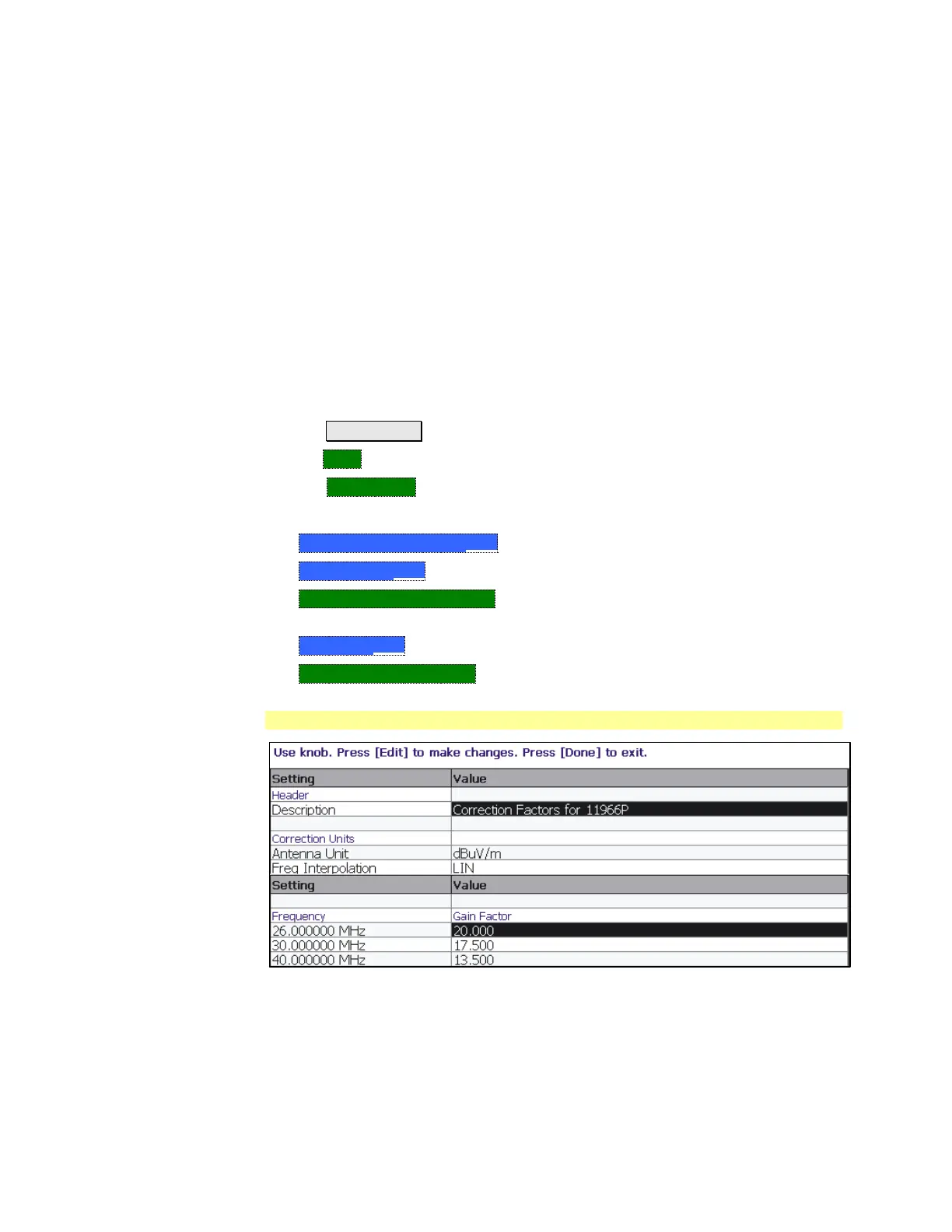
Using the Antenna/Cable Editor
Two (appended) pages of Antenna Editor
The Antenna Editor and the Cable Editor menus are identical. Both tables
include header information, and a Frequency/Value table.
 Loading...


