5 Verification and Performance Tests
Performance Verification Tests
162 U3606A User’s and Service Guide
3 Set the output voltage to the full rated value (30 V for S1 range) and
current to full scale.
4 Connect an additional electronic load across the front panel (red)
and (black) output terminals in parallel with a oscilloscope (see
Figure 5- 8 on page 145).
5 Operate the electronic load in transient operation mode between one
half of the output full rated value and the output full rated value at a
1 Hz rate with 50% duty cycle.
6 Set the oscilloscope for AC coupling, internal synchronization, and lock
on either the positive or negative load transient.
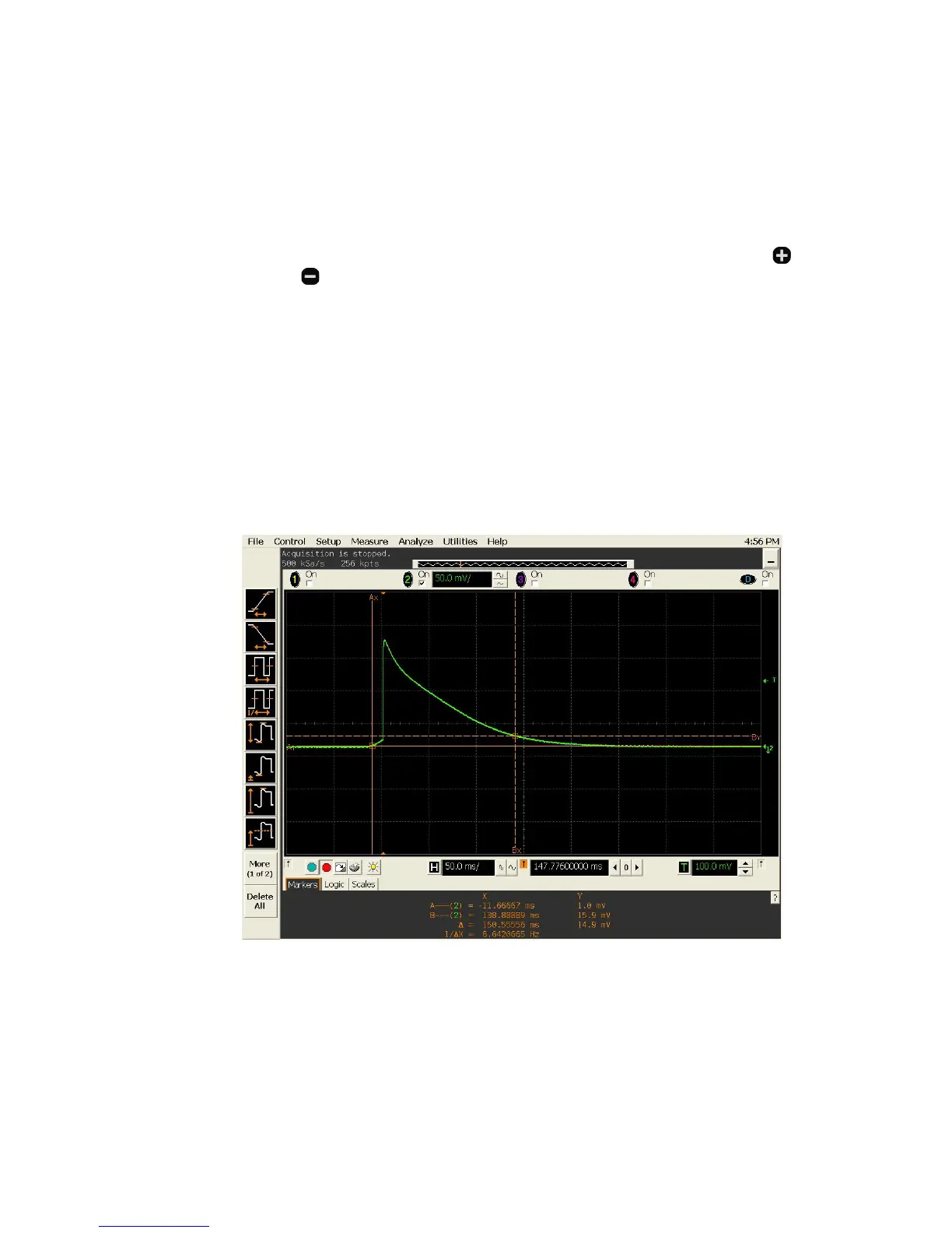
7 Adjust the oscilloscope to display transients as shown in Figure 5- 13.
Note that the pulse width (t
2
– t
1
) of the transients at 15 mV from the
base line should be no more than 300 ms for the output.
Figure 5-13 Load transient response time

 Loading...


