2 Digital Multimeter Operation
Making Measurements
52 U3606A User’s and Service Guide
Checking diodes
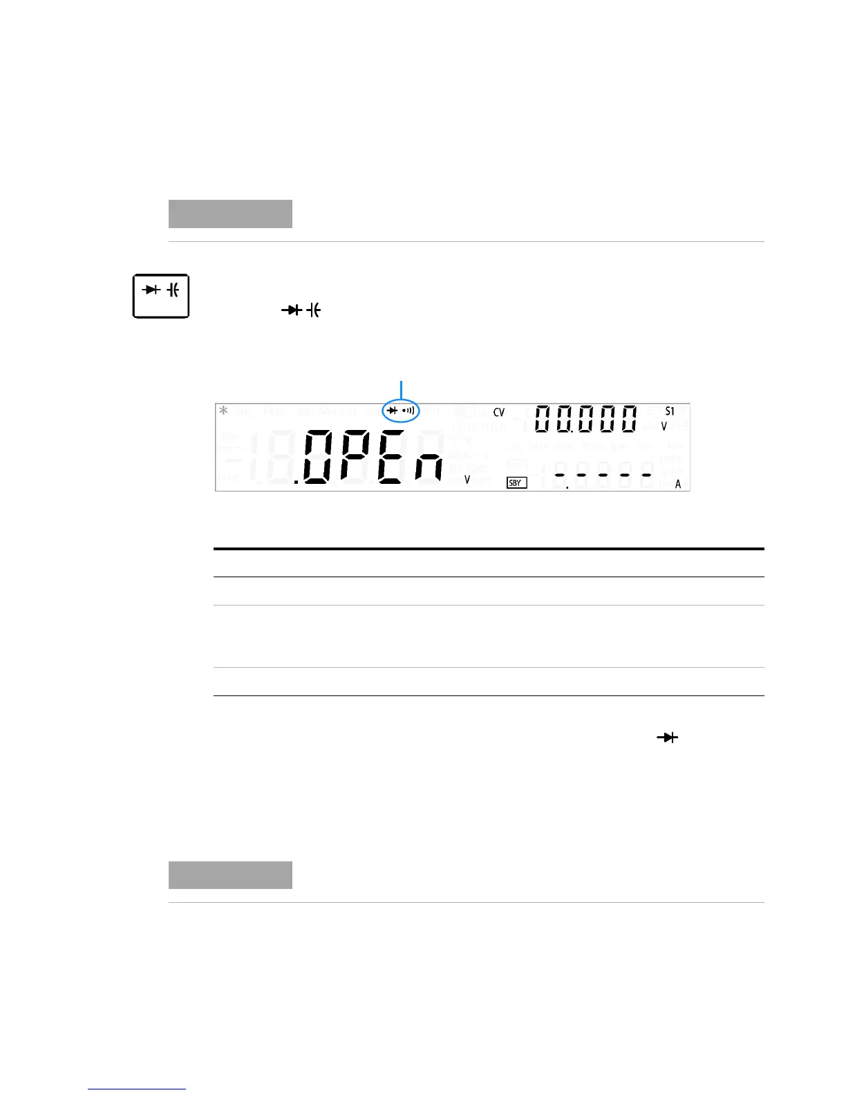
1 Press again (until the diode annunciator is shown on the
display) to make diode measurements.
2 Connect the red and black test leads to input terminals (red) and
LO (black) respectively.
3 Connect the other end of the red test lead to the positive terminal
(anode) of the diode and the black test lead to the negative terminal
(cathode). Refer to Figure 2-9 on page 51.
4 Read the display.
The resolution for diode tests is fixed to 3½ digits.
Table 2 - 11 Diode function summary
Item Description
Measurement method 0.83 mA ± 0.2% constant current source
Audible tone: • Continuous beep when level is below +50 mV DC
• Single tone for normal forward-biased diode or semiconductor
junction where 0.3 V ¤ reading ¤ 0.8 V
Input protection 1000 V
rms
on all ranges, < 0.3 A short circuit
The cathode of a diode is indicated with a band.