6 Calibration Procedures
Adjustments procedures
200 U3606A User’s and Service Guide
• An adjustment failure is indicated by a long beep, the primary
display showing “FAiL” and a calibration error number appearing in
the upper secondary display. Correct the problem and repeat this
procedure.
8 Repeat step 3 through step 7 for each gain adjustment point shown in
Table 6- 7.
9 Verify the DC current gain adjustments using the “DC current gain
verification test” on page 153.
AC current gain adjustment procedure
Review the “Test Considerations” on page 140 and “Gain adjustment
considerations” on page 191 sections before beginning this procedure.
1 Press twice to enter the AC current gain calibration. The AC
annunciator will be illuminated.
2 The primary display will show the uncalibrated value and the upper
secondary display will show the reference value of the adjustment item.
3 Configure each adjustment item shown in Table 6- 8.
4 Use or to select the adjustment item.
5 Apply the input signal shown in the “Input” column of Table 6- 8.
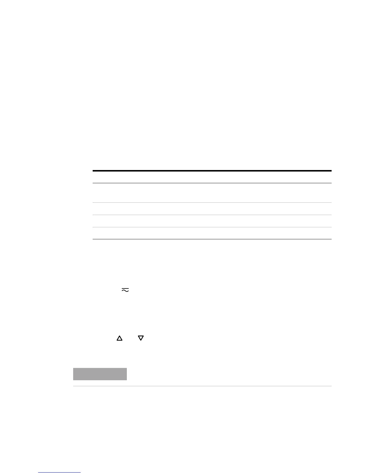
Table 6 - 7 DC current gain adjustment
Adjustment item Input current
OPEn
Input terminals open (remove any test leads or
shorting plugs from the input terminals)
10.0000 mA 10 mA
100.000 mA 100 mA
1000.00 mA 1000 mA
Always complete tests in the same order as shown in Table 6-8.