Calibration Procedures 6
Adjustments procedures
U3606A User’s and Service Guide 209
9 Verify the constant voltage adjustments using the “CV programming and
readback accuracy” on page 157.
CC output adjustment procedure — rear output terminals
Review the “Test Considerations” on page 140 and “Input Connections” on
page 141 sections before beginning this procedure.
1 Turn off the instrument and connect the rear panel + and
– output terminals to the I (red) and LO (black) input terminals.
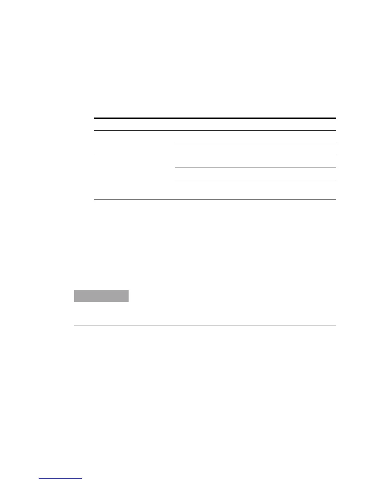
Table 6 - 12 Constant voltage output adjustment
Range Adjustment item Output voltage
S2 (8 V/3 A)
OUt-L 0 V
OUt-H 8 V
S1 (30 V/1 A)
OUt-L 0 V
OUt-H 30 V
LOAd
[1]
[1] See step 8 for information on how to connect the LOAd adjustment item.
30 V with additional
30 Ω, 50 W load
Ensure that the rear panel sense terminals (+S and –S) are shorted to the
rear panel output (+ and –) terminals. See “Remote sensing
connections” on page 100 for more information on how to connect the
load leads.