158 Rockwell Automation Publication 750-UM006C-EN-P - March 2022
Chapter 5 Drive Maintenance
8. Without removing the control cables attached to the TB1 terminal
block, disconnect the TB1 terminal block from the main control board.
9. Use a #2 Pozidriv, M3 x 7 tool to remove the listed power wires.
10. Use a 7 mm hex deep socket to remove the ground wires.
11. Remove the EMC kit. See Replace the EMC Kit (1CH030)
on
page 163 for additional information.
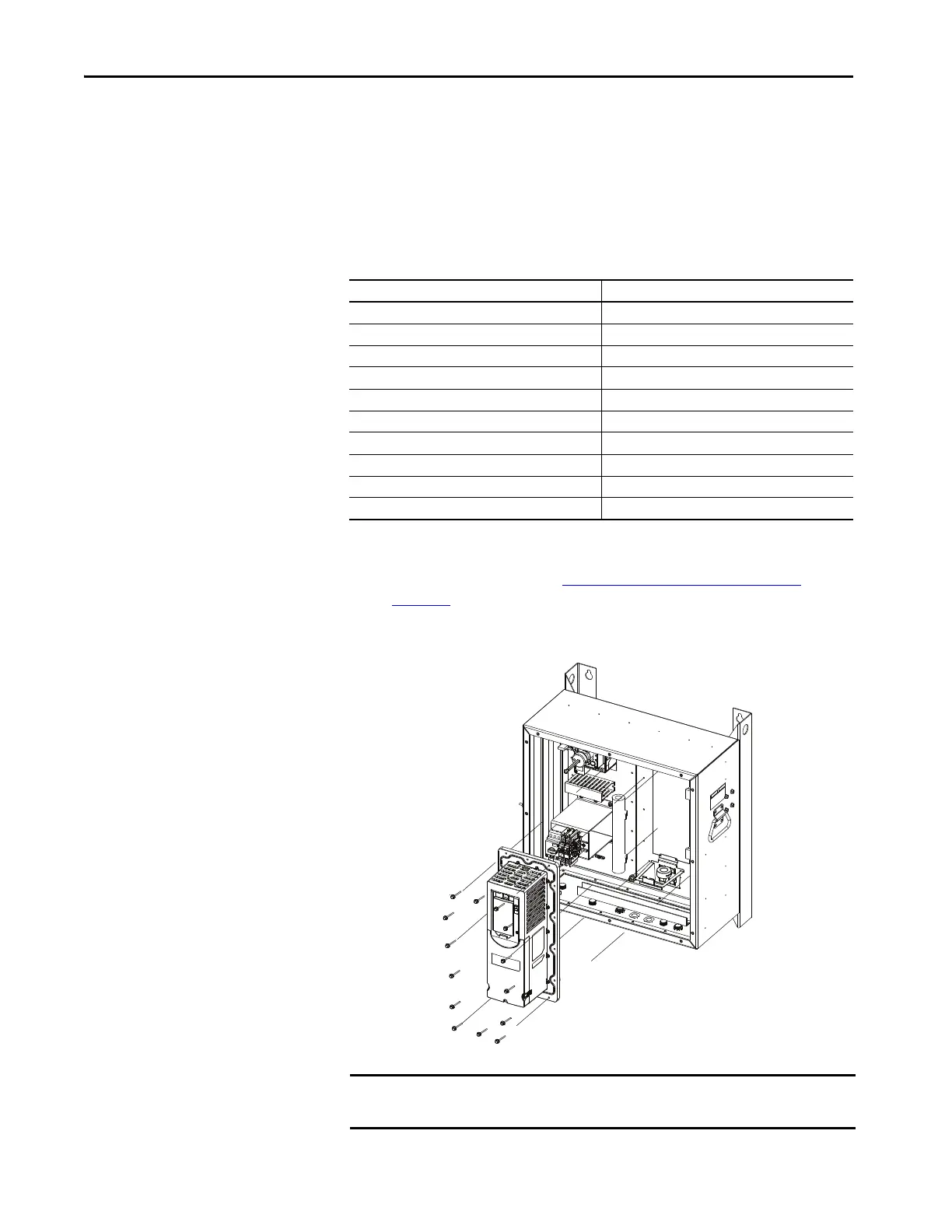
12. Use a T20 torque bit to remove the 14 screws that hold the drive to the
enclosure.
TIP To avoid the need to rewire the terminal blocks, verify terminal screws and
wires are secure. Terminal wiring does not need to be removed to replace
the PowerFlex 755 drive.
Wire Description Terminal Number
1EA030-R/L1 R/L1
1EA030-S/L2 S/L2
1EA030-T/L3 T/L3
1EA030-PE PE (LEFT SIDE)
1EA030-U U/T1
1EA030-V V/T2
1EA030-W W/T3
1EA030-PE PE (RIGHT SIDE)
1EA030-BR1 BR1
1EA030-BR2 BR2
IMPORTANT In the image, the covers are shown in place, the covers must be removed and
the terminal blocks disconnected to remove the drive.

 Loading...


