DC Asterion Series Overview
M330460-01 Rev A 1-7
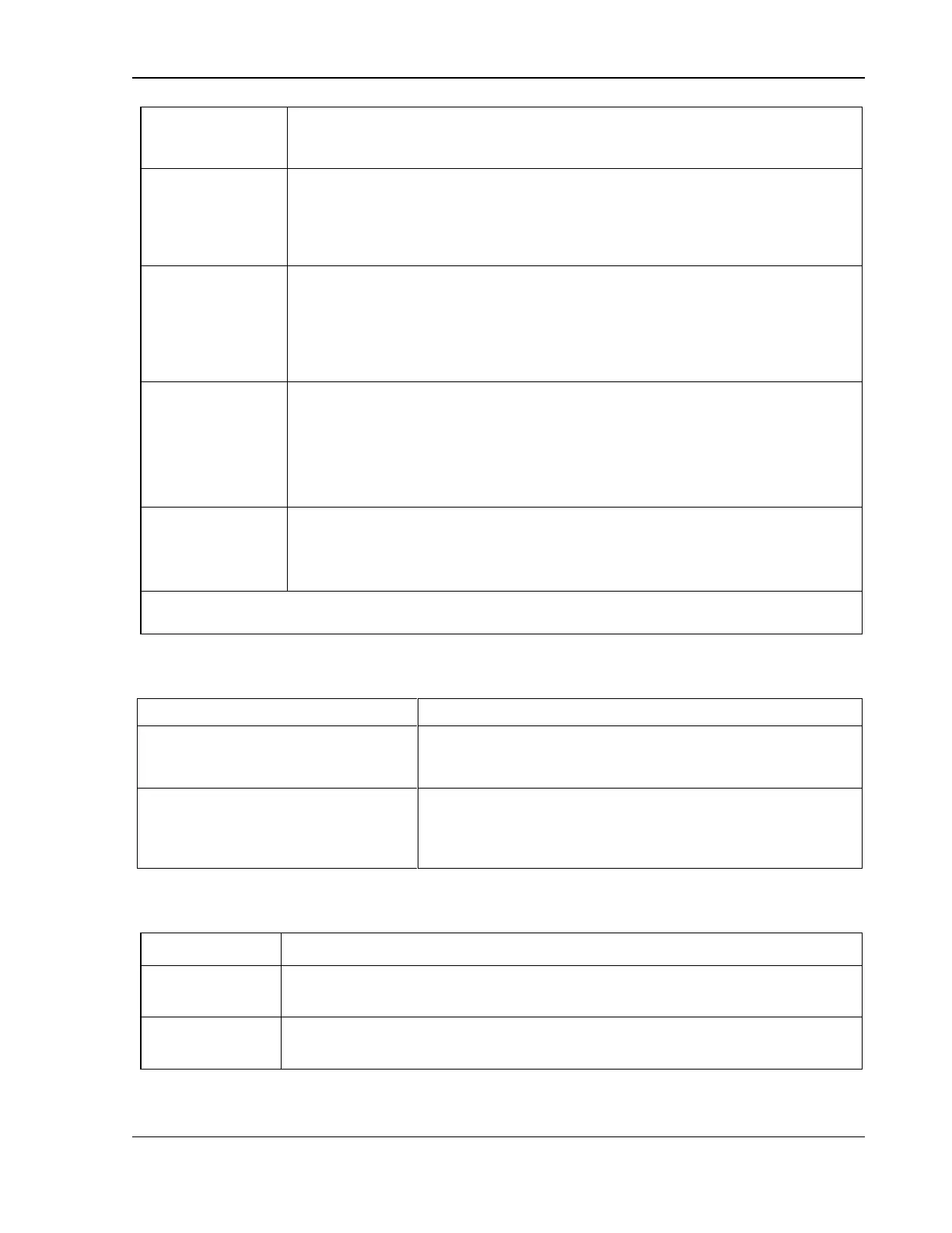
Internal to power supply, signal output is from driver with input connected to open-collector
of opto-isolator transistor
Voltage Rating: Maximum 30 V, Minimum 4.5V for Active High, Current Maximum 0.5 A
Output Signal, High state indicates fault state of the power supply. There is an Option to
feed User Power to the FAULT signal.
Internal to power supply, signal output is from driver with input connected to open-collector
of opto-isolator transistor
Voltage Rating: Maximum 30 V, Minimum 4.5V for Active High, Current Maximum 0.5 A
User
programmable
digital inputs
Four digital inputs to the power supply. Two of the digital inputs can be used as enable
signals for user programmable digital outputs.
Signal connects to Open-anode of opto-isolator diode with internal 1kΩ series resistor
internal to power supply
Voltage Rating: Maximum 24 V, Minimum -5V
Low state 0.3 V max, High State 2.7 V min
User
programmable
digital outputs
Four digital outputs that can be enabled/ disabled from the power supply. Two digital
outputs can be controlled by giving appropriate signals on User programmable digital
inputs. There is an Option to feed User Power to these digital outputs.
Voltage Rating: Min 4.5V or User fed voltage minus 1 V. User fed voltage can be of
maximum 30 V.
Current Maximum: 0.5 A
Two Auxiliary power outputs of 15 V and 5 V. These auxiliary power outputs can be
controlled from the power supply or by giving appropriate signals on the digital input enable
pins provided for the same.
Maximum current for the Auxiliary power output: 1 A
12)
Unit is rated for +/- 1% Accuracy at 5V/10V for Voltage Programming, and 5kOhm/10kOhm for Resistive
Programming
±600 V(PK), maximum, with respect to chassis ground.
Reference of standard Non-Isolated
Analog programming and external user
interface to output negative terminal
The standard Non-Isolated Analog programming and external user
interface signals are referenced to the negative output terminal and,
therefore, is not isolated from the output.
Isolation of optional Isolated Analog
programming and external user interface to
output negative terminal
1000 V(PK), maximum; optional Isolated Analog programming and
external user interface signals are galvanically isolated from negative
output terminal; operation of Isolated Analog Interface signals should
be at SELV safety voltage conditions to chassis ground.
1.2.9 Remote Control Digital Interface Characteristics
Ethernet 10BASE-T and 100BASE-T over twisted-pair cables compliant with IEEE 802.3;
Connector: 8P8C modular jack.
Serial interface compliant to USB 2.0;
Connector: Type-B receptacle.

 Loading...


