DC Asterion Series Overview
M330460-01 Rev A 2-17
2.12 Load Considerations
This section provides guidelines for incorporating protective diode networks at the output
of the power supply to prevent damage while driving inductive loads or loads having
stored energy that could be circulated back to the power supply.
2.12.1 Inductive and Stored-Energy Loads
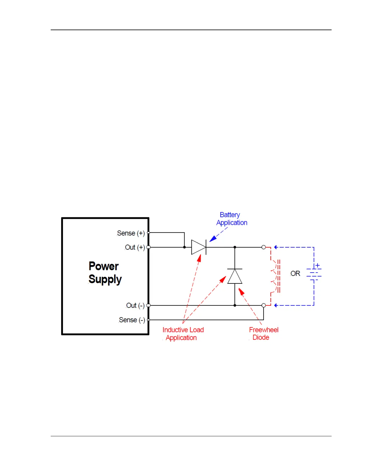
To prevent damage to the power supply from inductive voltage kickback, connect an
antiparallel diode (rated at greater than the supply’s output voltage and current)
across the output: Connect the cathode to the positive output and the anode to return.
Where positive load transients, such as back EMF from a motor might occur, or stored
energy is present such as a battery, a second blocking diode in series with the output is
recommended to protect the power supply. Refer to Figure 2-9.
2.12.1.1 BLOCKING AND ANTI-PARALLEL DIODES
Ensure that the chosen components are suitably rated for the inductance and
energy to be dissipated. The Peak Reverse Voltage ratings should be a minimum
of 2 times the Power Supply maximum output voltage. The Continuous Forward
Current ratings should be a minimum of 1.5 times the power supply maximum
output current. A heatsink may be required to dissipate the power caused by flow
of current.
Figure 2-9. Diode Connections
2.13 Rear Panel User Interface Connectors
The rear panel contains the connectors for the remote analog and external user control
interface, parallel unit connection interface and the digital communications interfaces
(LAN, USB, RS-232C, and optional IEEE-488).

 Loading...


