Overview DC Asterion Series
3-10 M330460-01 Rev A
In HW (Hardware) trigger mode, the ramp will be generated when
an active high pulse of 10ms is applied on the MOLEX connector
pin-8 (TRIGGER_IN) and pin-12 (DIN_RTN). Refer to Table 3–2
for PIN details.
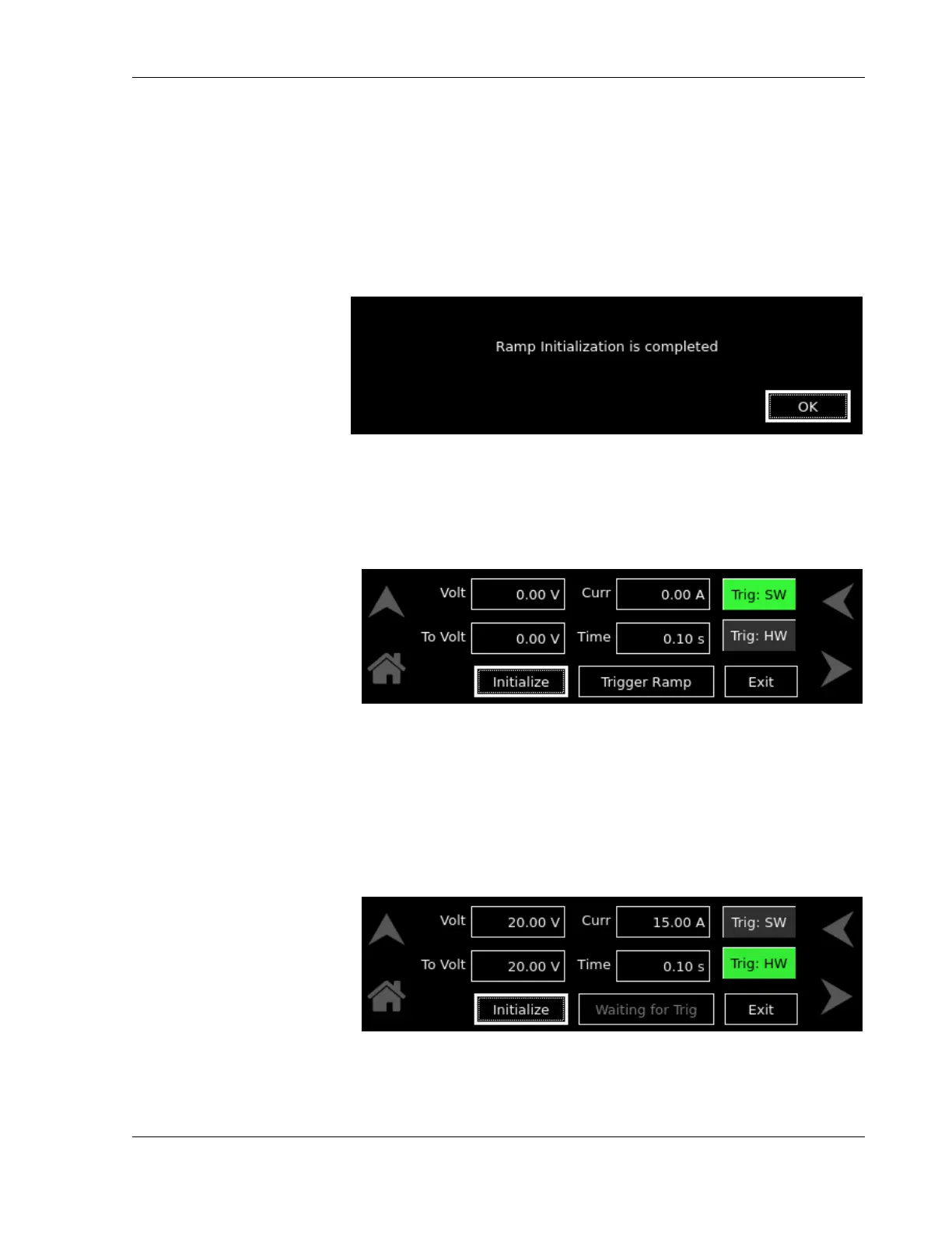
Initialize Initializes the set Ramp parameters. Refer to Figure 3-21.
Press OK to return.
Figure 3-21. Ramp-Screen (Initialization)
Trigger Ramp Generates the ramp in SW trigger mode. Trigger Ramp button
will only be enabled after Initialize button is pressed, Refer to
Figure 3-22.
Figure 3-22. Voltage Ramp-Screen (SW Trigger)
Waiting for Trig This field is displayed after Initialize button is pressed in HW trigger
Mode, refer to Figure 3-23. This shows that the supply is waiting for
an active high pulse of 10ms on the MOLEX connector pin-8
(TRIGGER_IN) and pin-12 (DIN_RTN) to generate the Voltage
Ramp. Refer to Table 3–2. Analog Programming Connector,
Designations and Functionsfor PIN details.
Figure 3-23. Voltage Ramp-Screen (HW Trigger)
Abort In SW trigger mode, when Trigger Ramp button is pressed,
Trigger Ramp button changes to Abort button.

 Loading...


