3 Pin Mating type header on the chassis
Mating connector Ametek P/N, 856-390-03
Mating Manufacturer P/N: Molex 39-01-4031
Crimp Pin Ametek P/N, 856-390-00
Mating Manufacturer P/N: Molex 39-00-0182
Table 2-6. Analog Programming and External User Control Interface
Connector Type
Output voltage sensing is user-selectable to be either local sense or remote sense.
Sensing provides the signal for measurement of the output voltage and determines
the physical point where the output voltage is precisely regulated. Local sense is at
the rear panel output connector, while remote sense is at the load, through a cable
connection from the rear panel remote sense connector. Based on the user selection
(local or remote) corresponding sense signal is used by the controller as the voltage
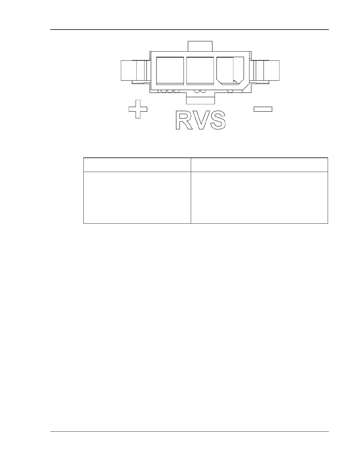
feedback. Figure 2-7, shows the remote sense connector at the rear panel of the power
supply.
Remote sensing is used to compensate for the voltage drop that occurs across the
wires connecting the load to the output of the power source. A separate pair of wires
is routed to measure the voltage at the terminals of the load where precise regulation
of the output voltage is desired. The remote sense leads are connected at the remote
sense connector on the rear panel; refer Figure 2-7. Connect the terminal, Sense
Positive (+), to the point at the load that is connected to the Output Positive terminal,
and the terminal, Sense Negative (-), to the point at the load that is connected to Output
Negative terminal.
On selecting the remote sense, if the difference between the remote sense and the
local sense exceeds more than 5% of the rated output voltage, then the unit would go
to fault state. The fault can arise due any of the following conditions.

 Loading...


