DC Asterion Series Overview
M330460-01 Rev A 3-23
Entry Description
5V Sets the 5V Auxiliary Output to ON or OFF state. 5V will be available
on the Analog Programming connector between Pin 43 (source) and
Pin 29 (return).
15V Sets the 15V Auxiliary Output to ON or OFF state. 15V will be available
on the Analog Programming connector between Pin 42 (source) and
Pin 41 (return).
3.1.8 Control Interface Screen
The Control Interface screen provides the ability to configure the power source for
remote control through the data communications interfaces. From control Interface
screen, user can also configure Analog Programming feature to program the power
supply parameters from external sources such as voltage, Resistance and 4-20mA.
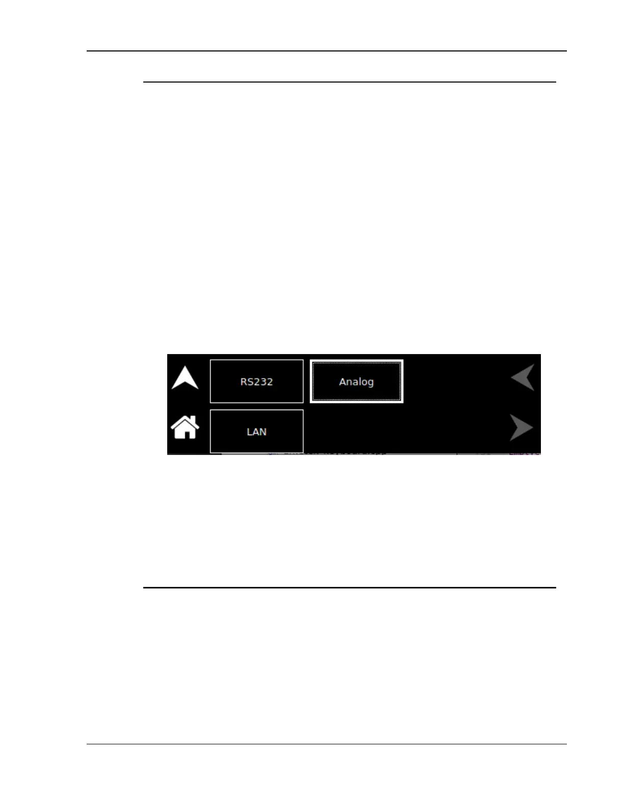
The top-level menu of the Control Interface screen is shown in Figure 3-55.
Refer to Section 3.1.2.1 for navigating to Control Interface Screen.
Figure 3-55. Control Interface Screen Top-Level Menu
The following menus are available in the Control Interface Screen top-level menu:
RS232, LAN and Analog.
3.1.8.1 RS232
Entry Description
RS232 Settings Lists the configured Baud Rate, Stop Bits, Bits and Parity for the
RS232 digital interface, refer to Figure 3-56 and Figure 3-57.

 Loading...


