Do you have a question about the Amsco 110LS and is the answer not in the manual?
Details regarding essential preventive maintenance and service agreements for sterilizer upkeep.
Describes the intended applications and configurations of the sterilizer for various processes.
A step-by-step checklist to verify correct sterilizer installation and component setup.
Details the electrical, mechanical, and environmental specifications of the sterilizer unit.
Provides recommended settings for sterilization cycles like prevacuum, gravity, and liquid.
Describes methods for verifying the sterilization process efficacy, including monitors and tests.
Offers advice on optimizing sterilization results, especially for specific container types.
Provides specific techniques and safety recommendations for sterilizing liquids safely.
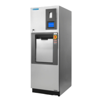
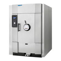
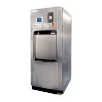
Identifies and describes the major components and controls of the sterilizer unit.
Introduces the control panel as the central interface for all sterilizer functions.
Details how to select and change the display and printout language for user convenience.
Provides instructions and safety precautions for manually operating the sterilizer door.
Outlines the procedure for emergency door operation and associated safety warnings.
Explains the function and operation of the optional electric steam generator.
Guides the user through the process of setting up and running the generator flush.
Describes how automatic generator flushing operates based on utility shutdown settings.
Lists and explains potential alarms related to the generator flush cycle.
Introduces the touch screen interface and its basic operation for user interaction.
Explains how to enter operating modes and select sterilization cycles.
Describes how to access status screens for pressure, temperature, and machine I/O.
Explains how to operate the printer for paper feed, cutting, and duplicate prints.
Guides on copying cycle data and history to a USB drive for backup.
Instructions on how to read and analyze cycle graph data from a PC.
Outlines essential checks and procedures to perform before operating the sterilizer.
Explains the steps and safety precautions for running a Gravity cycle.
Explains the steps and safety precautions for running a Prevac cycle.
Explains the steps and safety precautions for running a Liquid cycle.
Details the procedure and safety for the optional Isothermal cycle.
Describes the Warmup cycle used before DART or Bowie-Dick tests.
Explains the DART and Bowie-Dick cycles for air removal testing.
Details the process and importance of running a Leak Test cycle for system integrity.
Explains the Lab Waste cycle for sterilizing laboratory waste.
Describes the USP 660 cycle for glass delamination testing.
Explains the ATF 1 cycle for XCell™ ATF System sterilization.
Explains the ATF 2 cycle for XCell™ ATF System sterilization.
Details the Decontamination cycle for processing loads in BSL applications.
Explains the Liquid Air Cool cycle for reducing liquid load cooling time.
Describes reasons for cycle abortion and how it is indicated.
Details features and functionality of sterilizers equipped with double doors.
Explains the use of load probes and Fo values for sterilization time measurement.
Describes the function of the separate steam feed option for jacket control.
Explains how to access the Options screen for various settings and functions.
Details how to enter Supervisor Mode for system configuration and advanced settings.
Details the 21 CFR Part 11 feature for record retention and traceability.
Describes non-aborting alarms that occur while a cycle is in progress.
Lists aborting alarms that halt the sterilization cycle due to critical issues.
Describes alarms that can occur when the sterilizer is not actively running a cycle.
Emphasizes the importance of scheduled preventive maintenance by qualified technicians.
Step-by-step instructions for replacing the printer paper roll.
Details the procedure for cleaning the chamber drain strainer.
Explains how to flush the chamber drain when it becomes clogged.
Information on ordering replacement parts and supplies for the unit.
Lists specifications for the Programmable Logic Controller (PLC) used in the system.
Provides specifications for the RTD module used for temperature sensing.
Lists specifications for the AC output relay module.
Provides specifications for the PanelView Plus display unit.
Lists PLC tag locations for various data points used in SCADA systems.
| Brand | Amsco |
|---|---|
| Model | 110LS |
| Category | Laboratory Equipment |
| Language | English |