4-2
387366-389 Operator Manual Operator Instructions
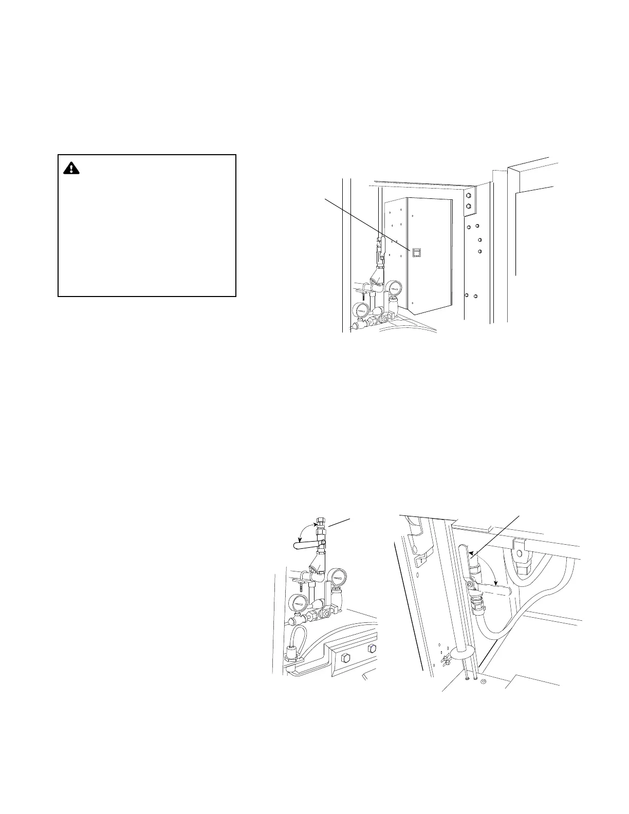
4.1.1 Main Power
Disconnect Switch
The main power disconnect switch, located behind the front cabinet
panel, controls power supply to the sterilizer and control system (see
F
IGURE 4-2).
Important: This switch should remain in the ON position at all times
for normal unit operation.
Figure 4-2. Main Power Disconnect Switch Location
4.1.2 Supply Valves Supply valves (see FIGURE 4-3) to the sterilizer are located behind
the front cabinet panel. Steam supply valve is located above the
chamber door; water supply valve is located below the chamber
door).
NOTE: If unit is equipped with electric steam generator, see
S
ECTION 4.6, OPTIONAL ELECTRIC STEAM GENERATOR, for location of
the generator supply valve.
Important: Both supply valves to the sterilizer should remain in the
ON position at all times for normal unit operation.
Figure 4-3. Steam and Water Supply Valves
WARNING – ELECTRIC
SHOCK AND BURN HAZARD:
Disconnect all utilities to
sterilizer before servicing.
Do not service the sterilizer
unless all utilities have been
properly locked out. Always
follow appropriate Lockout-
Tagout and electrical safety-
related work practice
standards.
Main Power
Disconnect Switch
Steam Supply
Valve
ON
OFF
Steam Valve Located
Above Chamber Door
Water Supply
Valve
ON
OFF
Water Valve Located Below Chamber Door