Do you have a question about the Amsco C Series and is the answer not in the manual?
Information on preventive maintenance and STERIS service.
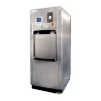
Details the intended use of the AMSCO C Series Sterilizer.
Checklist to ensure installation is complete and correct.
Importance of adequate service clearance for installation and maintenance.
Requirements for feed water, steam supply, and drain piping.
Electrical service requirements for single-phase power.
Final checks before operating the sterilizer.
Procedures for initial cycle operation and testing.
Dimensions of the 16" and 20" sterilizer models.
Weight specifications for different sterilizer configurations.
Electrical, water, and steam utility requirements.
Environmental operating conditions for the sterilizer.
General information on sterilization preparation and storage.
Procedures for using the sterilizer for immediate use cycles.
Methods for verifying the sterilization process, including biological monitoring.
Procedure for conducting the Dart (Bowie-Dick) test.
Use of biological monitors for sterilization verification.
Testing the efficiency of prevacuum cycles.
Procedure for testing the vacuum integrity of the sterilizer.
Best practices for achieving reproducible sterilization results.
Specific techniques for sterilizing liquids.
Important considerations for sterilizing liquids safely.
Guidelines for monitoring sterilization of implantable devices.
General overview of control locations and functions.
Identification of main controls like power disconnect and valves.
Explanation of out-of-cycle and in-cycle control displays.
How the sterilizer displays alarm conditions and troubleshooting steps.
Description of the control panel used for starting, aborting, and setting cycles.
How to select and start sterilization cycles using touchpads.
Pads used for changing cycle parameters like name, temperature, time.
Procedure for using the abort touchpad to end a cycle prematurely.
Functions of the printer for recording cycle data.
Information reported by the printer, including load numbers and status lines.
Operation of the sterilizer door using the foot pedal.
Procedure to manually open the door in emergency situations.
Safety feature to shut down the sterilizer completely in emergencies.
Procedure for resetting the emergency stop switch using a key.
Function of the guard to prevent accidental pressing of the stop switch.
Location of the emergency stop label.
Information about the optional electric steam generator and its maintenance.
Pre-operation checks and procedures.
Guidelines for preparing and packaging items for sterilization.
Recommendations for loading items into the sterilizer chamber.
Procedures for safely unloading the sterilizer after a cycle.
Step-by-step instructions for loading the sterilizer using a loading car.
Step-by-step instructions for unloading the sterilizer using a loading car.
Procedures for loading and unloading using rack and shelf options.
Details on factory-set prevacuum cycles and their parameters.
Specific instructions and cycle progression for prevacuum cycles.
Specific instructions and cycle progression for gravity cycles.
Specific procedures and safety precautions for the liquid cycle.
Details on factory-set SFPP cycles and their parameters.
Specific instructions for SFPP cycles including safety warnings.
Procedures for running factory-programmed test cycles.
Detailed procedure for conducting the Dart (Bowie-Dick) test.
Procedure for performing a weekly vacuum leak test.
How to cancel or abort a sterilization cycle.
Visual representation of sterilizer cycle phases and parameters.
How to adjust cycle values like name, temperature, time, and dry time.
Step-by-step guide for changing cycle values.
General steps for accessing and changing cycle values.
Specifics on adjusting sterilize time and dry time for cycles.
Visual flowchart for accessing and changing cycle values.
How to add custom names to cycle selection buttons.
Procedure for setting the sterilizer's internal time and date.
Overview of machine setup options affecting sterilizer operation.
How to enable or disable the access code for security.
Function to secure setup options and prevent unauthorized changes.
How to control utilities automatically based on schedule.
Setting up the automatic generator flush cycle.
Setting the time and duration for the steam generator flush cycle.
Selecting display and printout languages.
Assigning an identifying code to the sterilizer for printouts.
Selecting the time display format (AM/PM or 24 HOUR).
Selecting the printout format (FULL or CONDENSED) to conserve paper.
Adjusting volume levels for touchpad, end-of-cycle, and alarm signals.
Selecting units for temperature (F/C) and pressure (psig/mbar/psia).
Selecting the date display format (M-D-Y, D-M-Y, etc.).
Setting the sterilizer to automatically provide an extra printout after a cycle.
Procedures for exiting the Change Values and returning to previous screens.
Schedule for periodic preventive maintenance tasks.
Daily checks and cleaning tasks for the sterilizer.
Checking the printer paper roll status.
Procedure for cleaning the chamber drain strainer daily.
Procedure for flushing the chamber drain line.
Procedures for cleaning the sterilizer chamber.
Maintenance procedures for the printer.
Step-by-step guide for changing the printer paper roll.
Procedure for changing the printer ink cartridge.
Introduction to alarm conditions and troubleshooting.
Understanding the components of a typical alarm screen.
Information found in typical alarm printouts.
Alarms that occur while a sterilization cycle is in progress.
Alarm condition for failure to reach temperature within allotted time.
Alarm for failure to exhaust to 4 psig within the allotted time.
Alarm for failure to reach evacuation level within the allotted time.
Alarm for failure to air break vacuum within the allotted time.
Alarm for chamber temperature dropping below sterilize temperature.
Alarm for chamber temperature exceeding maximum sterilize temperature.
Alarm when steam pressure in the door seal drops below 5 psig.
Alarm for readings outside normal steam range during sterilize phase.
Alarm for liquid cycle exhaust rate being too fast.
Alarm for liquid cycle exhaust rate being too slow.
Alarm when temperature probes differ by more than 1°F.
Alarm indicating failure of the generator drain temperature probe.
Alarms that occur when the sterilizer is not processing a cycle.
Alarm if the door switch does not make contact within the allotted time.
Alarm if the door switch does not open within the allotted time.
Alarm if 2 psig pressure is sensed in the chamber when not in cycle.
Alarm if waste line temperature reading is outside normal range.
Alarm if atmospheric pressure differs from calibrated value.
Alarm indicating I/O board communication failure with control boards.
Alarm for failure of the Read Only Memory on the main control board.
Alarm for failure of the Random Access Memory on the main control board.
Alarm for failure of the Analog to Digital Board on the main control board.
Alarm indicating the emergency stop switch has been pressed.
Alarms related to sensor readings during or out of cycle.
Alarm if excess water is sensed in the chamber.
Alarm if jacket does not reach set temperature within allotted time.
Alarm if door seal does not reach 5 psig within allotted time.
Alarm if door seal pressure does not drop below 5 psig within allotted time.
Alarm if chamber pressure reading is outside the normal range.
Alarm if chamber temperature reading is outside the normal range.
Alarm if jacket temperature reading is outside the normal range.
Alarm if door switch contact is made but switch remains open.
Alarm if door seal A switch fails to close.
Alarm if main control circuit board temperature exceeds environmental limits.
Introduction to advanced servicing procedures.
Procedure for replacing the bacterial air filter.
Procedure for cleaning the sterilizer strainers.
Procedure for replacing the sterilizer door seal.
Procedure for replacing the steam trap assembly.
Procedure for cleaning or replacing piping check valves.
Instructions for rebuilding solenoid valves using repair kits.
Procedure for testing the safety valve.
Information on ordering replacement parts and supply products.
Guidelines for disposing of waste materials from the sterilizer.
| Brand | Amsco |
|---|---|
| Model | C Series |
| Category | Laboratory Equipment |
| Language | English |