Home
Amsco
Laboratory Equipment
C Series
Amsco C Series User Manual
4
of 1
of 1 rating
154 pages
Give review
Manual
Specs
To Next Page
To Next Page
To Previous Page
To Previous Page
Loading...
8-8
P129394-176
Operator Manual
Routine Maintenance
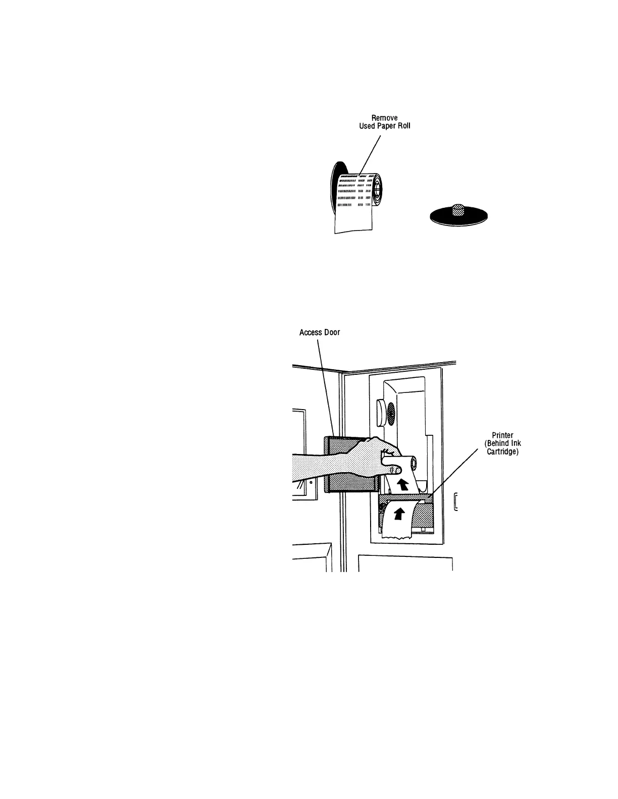
3.
P
ull off right
end of s
pool and rem
ove used p
aper roll fro
m
spindle.
4.
Open access door and remove previou
s paper roll, gently
pulling any remaining paper
up and out of printer.
Figure 8-4. Remo
ve P
aper Fr
om Spool
Figure 8-5. Remo
ve Remaining Previous P
aper
113
115
Table of Contents
Table of Contents
6
Safety Precautions
13
Symbol Definitions
16
Table 2-1. Symbol Definitions
16
Installation Verification
17
Service Clearance
17
Plumbing Services
17
Electrical Service
18
Sterilizer Final Check
18
Cycle Operation
18
Technical Specifications
19
Overall Size
19
Weight (Fully Loaded)
19
Utility Requirements
19
Environmental Conditions
19
Techniques of Sterilization
20
General
20
Table 4-1. AMSCO C Series Prevacuum Sterilizer Cycles
20
Table 4-2. AMSCO C Series SFPP Sterilizer Cycles
22
Immediate Use
23
Control Measures for Verifying Sterilization Process
23
Biological Monitors
24
Testing for Prevacuum Efficiency
24
Dart (Bowie-Dick) Test
24
Vacuum Leak Test
25
Recommendations for the Sterilization Process
25
Techniques of Sterilization for Liquid Cycle
26
Table 4-3. Liquid Cycle Processing Guidelines
26
Recommendations for Sterilizing Liquids
27
Sterilization of Implantable Devices
27
Figure 4-1. Vented Closures
27
Component Identification
28
Figure 5-1. AMSCO C Series Small Steam Sterilizer Control Components
28
General
29
Main Sterilizer and Cycle Controls
29
Figure 5-2. Basic Controls
30
Control Displays
31
Figure 5-3. Typical Out-Of-Cycle and In-Cycle Displays
31
Alarm Displays
32
Figure 5-4. Alarm Display Examples
32
Operating End Control Panel
33
Figure 5-5. Control Panel
34
Cycle Selection Touch-Screen Pads
35
Figure 5-6. Cycle Selection Touchpads
35
Values Touch-Screen Pads
36
Figure 5-7. Values Touch-Screen Pads
36
Abort Touch-Screen Pad
37
Figure 5-8. Cycle Abort Touch-Screen Pad
37
Printer
38
Printouts
39
Figure 5-9. Typical Printout
40
Power-Door Operation
41
Figure 5-10. Power Door Floor Pedal
41
Emergency Door Opening Procedure
42
Figure 5-11. Emergency Door Opening Procedure
42
Emergency Stop Switch
43
Figure 5-12. Emergency Stop Switch, Key and Guard
43
Figure 5-13. Press Abort Button to End Cycles When Needed
43
Emergency Stop Key
44
Emergency Stop Guard
44
Emergency Stop Label
44
Figure 5-14. Emergency Stop Label
44
Optional Electric Steam Generator
45
Before Operating the Sterilizer
47
Sterilizer Operation
47
Figure 6-1. Utility Supply Valves and Basic Sterilizer Controls
48
Preparing Loads for Sterilization Cycles
49
Guidelines for Placement of Various Loads
49
Unloading the Sterilizer
50
Loading Car Instructions: Loading
51
Figure 6-2. Align Loading Car with Chamber Opening
51
Loading Car Instructions: Unloading
52
Loading/Unloading Sterilizer: Rack and Shelves
52
Prevacuum Sterilizer Cycles
53
Figure 6-3. Sterilizer Chamber Equipped with Rack and Shelves
53
Table 6-1. Factory-Set Prevacuum Cycles and Cycle Values
54
Prevac Cycles
55
Figure 6-5. Typical Prevacuum Cycle Printouts
56
Table 6-2. Factory-Set Gravity Cycles and Cycle Values
57
Gravity Cycles
58
Figure 6-7. Typical Gravity Cycle Printout
59
Table 6-3. Factory-Set Optional Liquid Cycle and Cycle Values
60
Liquid Cycle
61
Figure 6-9. Typical Printout of a Liquid Cycle
62
SFPP Sterilizer Cycles
63
Table 6-4. Factory-Set SFPP Sterilizer Cycles and Cycle Values
64
SFPP Cycles
65
Figure 6-11. Typical Printouts - 270°F SFPP and 275° SFPP Cycles
66
Test Cycles
67
Table 6-5. Test Cycles
67
Dart (Bowie-Dick) Test
68
Figure 6-13. Dart (Bowie-Dick) Test Cycle Printout
70
Vacuum Leak Test
71
Figure 6-14. Typical Printout of a Leak Test Cycle
72
Aborting Cycles
73
Cycle Graphs
74
Figure 6-15. Cycle Graph - 270°F or 275°F Prevacuum and Dart (Bowie-Dick) Cycles
74
Figure 6-16. Cycle Graph - Gravity Cycle
74
Figure 6-17. Cycle Graph - Leak Test
75
Figure 6-18. Cycle Graph - Steam Flush Pressure Pulse (SFPP) Cycles
75
Figure 6-19. Cycle Graph - Liquid Cycle
76
Cycle and Control Value Programming
77
Change Values
77
Change Cycle Values
78
Overview
78
Adjusting Cycle Sterilize Time and Dry Time
78
Table 7-1. Adjustment Ranges for Cycle Values
79
Step by Step Flowchart
80
Entering Custom Cycle Names
83
Figure 7-4. Enter or Change Custom Cycle Names
83
Change Time and Date
84
Change Machine Setup
87
Table 7-2. Change Machine Setup
87
Access Code
88
Lockout
90
Utilities Control
92
Steam Generator Flush and Drain Set up
96
Table 7-3. Required Feed Water Quality for Carbon Steel Steam Generators
96
Steam Generator Flush Cycle
97
Figure 7-5. Generator Flush Duration Time Control Screen
97
Language
98
Machine Number
99
Time Format
99
Print Format
100
Figure 7-6. Sample Full and Condensed Printouts
102
Audible Signals
103
Units
104
Date Format
104
Duplicate Print
105
Leaving Change Values
106
Routine Maintenance
107
Preventive Maintenance Schedule
107
Table 8-1. Preventive Maintenance
107
Daily Maintenance Procedures
109
Check Printer Paper Supply
109
Clean Chamber Drain Strainer
109
Figure 8-1. Remove Chamber Drain Strainer
109
Weekly Maintenance Procedure: Flush Chamber Drain
110
Chamber Cleaning
111
Printer Maintenance
113
Change Printer Paper Roll
113
Figure 8-2. Tear Paper in Printer
113
Figure 8-3. Remove Take up Spool
113
Figure 8-4. Remove Paper from Spool
114
Figure 8-5. Remove Remaining Previous Paper
114
Figure 8-6. Insert New Paper Roll
115
Figure 8-7. Insert Paper through Printer Slot
115
Figure 8-8. Press Paper Feed Touch Screen Button
116
Figure 8-9. Insert Paper into Take up Spool
117
Figure 8-10. Rotate to Secure Paper on Spool
117
Change Printer Ink Cartridge
118
Figure 8-11. Reinstall Take up Spool
118
Figure 8-12. Tear Paper
118
Figure 8-13. Press on End of Cartridge
119
Figure 8-14. Remove Cartridge
119
Figure 8-15. Press New Cartridge into Place
120
Figure 8-16. Tighten Cartridge Ribbon
120
Troubleshooting
121
General
121
Typical Alarm Screen
121
Figure 9-1. Typical Alarm Screen
121
Typical Alarm Printout
122
In-Cycle Alarms
122
Too Long in Charge
122
Figure 9-2. Typical Alarm Printout
122
Too Long in Exhaust
123
Too Long in Evacuation
123
Too Long in Air Break
124
Under Sterilize Temperature
125
Over Sterilize Temperature
126
Door Unsealed
127
Chamber Pressure/Temperature Failure
127
Exhaust Rate too Fast
128
Exhaust Rate too Slow
129
Recorder Deviation Alarm
129
Generator Drain Temperature Probe Failure Alarm
130
Out-Of-Cycle Alarms
131
Too Long to Close Door
131
Too Long to Open Door
132
Pressure in Chamber
133
Waste Temperature Probe Failure
134
Atmospheric Pressure Alarm
134
Input/Output Board #1 Communication Failure
135
ROM Failure
136
RAM Failure
136
ADC Failure
136
Emergency Stop Switch Pressed
137
Sensor Alarms
138
Water in Chamber
138
Too Long in Jacket Charge
139
Too Long to Seal Door
139
Too Long to Unseal Door
140
Chamber Pressure Transducer Failure
141
Chamber Temperature Probe Failure
141
Jacket Temperature Probe Failure
142
Door Switch Failure
143
Door Seal a Switch Malfunction
144
Board Overtemp Failure
144
Service Procedures
145
General
145
Air Filter Replacement
145
Figure 10-1. Serviceable Components
146
Clean Strainers
147
Figure 10-2. Remove Door Seal
147
Figure 10-3. Location of Seal Lot Data and Reference Indicators
147
Door Seal Replacement Procedure
148
Steam Trap Replacement
149
Clean or Replace Piping Check Valves
149
Figure 10-4. Steam Trap
149
Rebuild Solenoid Valves
150
Safety Valve Test
150
Figure 10-5. Internal Pilot-Operated Solenoid Valve
150
Recommended Spare Parts
151
Table 10-1. Replacement Parts AMSCO C Series Small Steam Sterilizer 16 X 16" (406 X 406 MM) and 20 X 20" (508 X 508 MM)
152
Waste Products Disposal
154
4
Based on 1 rating
Ask a question
Give review
Questions and Answers:
Need help?
Do you have a question about the Amsco C Series and is the answer not in the manual?
Ask a question
Amsco C Series Specifications
General
Brand
Amsco
Model
C Series
Category
Laboratory Equipment
Language
English
Related product manuals
Amsco 110LS
194 pages
Amsco STERIS
48 pages
Amsco Century
189 pages
Amsco HC-1500
176 pages
Amsco RELIANCE 444 HTM
36 pages
Amsco EAGLE SERIES 3021
32 pages
Amsco EAGLE SERIES 3023
32 pages
Amsco EAGLE SERIES 3053
32 pages
Amsco EAGLE SERIES 3043
32 pages
Amsco EAGLE SERIES 3041
32 pages
Amsco EAGLE SERIES 3011
32 pages
Amsco EAGLE SERIES 3013
32 pages