Preliminary Technical Data UG-1828
Rev. PrB | Page 129 of 277
signal might be transmitted out through the antenna. Although the power level of calibration signal is set as low as possible, user should
make sure that this will not cause any problem when using this option.
It is important that a suitable attenuator be chosen between the power amplifier output and the observation channel input. This is to
prevent transmit data from saturating the observation channel input. The following paragraph summarizes the external system
requirement.
External system requirement: a suitable attenuator must be chosen between the power amplifier output and the observation channel
input to prevent transmit data from saturating the observation channel input. The LNA (or RF switch if no LNA presented externally)
for the loopback path should be switched off to avoid receiving signals from RF port.
System Considerations for Receiver Initial Calibrations
In this section, similarly, high level block diagrams are used to show the device configurations and external system requirements for
receiver initial calibrations. In all the diagrams, grayed-out lines and blocks are not active in the calibration. Blue blocks are related
calibrations. It should be noted that the ADRV9001 ARM performs each of the calibrations. It is tasked with configuring the ADRV9001
device as per the diagrams below, with respect to enabling/disabling paths, and so on. No user input is required in this regard. However,
it is important that the user ensures that external system conditions are met, such as having the receiver input properly terminated for Rx
initialization calibrations.
Among 11 different receiver initial calibrations, RX_HPADC_RC, RX_HPADC_FLASH, RX_HPADC_DAC (not enabled) and
RX_LPADC calibration are performed in the analog domain and the corrections are applied to HP ADC or LP ADC (based on which
one is used), while all other receiver initial calibrations are performed in the digital domain. For RX_QEC_FIC and RX_QEC_TCAL, the
calibration results are applied in digital domain for correction. For RX_DCC, RX_RF_DC_OFFSET, RX_TIA_CUTOFF, RX_
GROUP_DELAY and RX_QEC_ILB_LO_DELAY, the calibration results are applied in the analog domain for correction. Figure 130
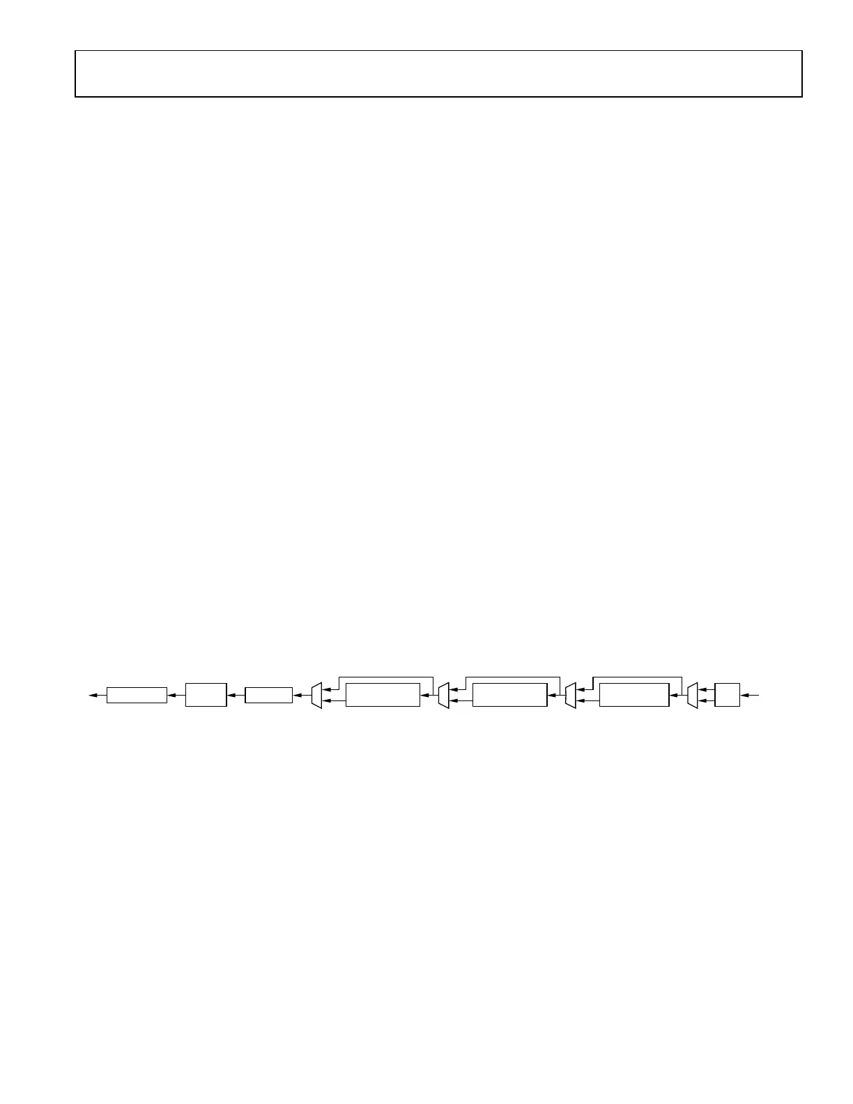
shows the high level block diagram of system configurations for receiver initial calibrations. Note different calibration performs at
different locations in the receiver datapath which is simplified in Figure 130.
DATA PORT
CMOS-SSI OR
LVDS-SSI
0°
90°
To BBP
LNA
ADRV9001 Rx
RX_QEC_FIC
RX_QEC_TCAL
RX_RF_DC_OFFSET
RX_TIA_CUTOFF
RX_GROUP_DELAY
RX_DCC
RX_QEC_ILB_LO_DELAY
LNA SWITCH OFF
LPF
LO1
LO2
LPF
24159-103
HP
ADC
HP
ADC
CAL
PLL
HPADC_RC
HPADC_FLASH
LPADC
LP
ADC
LP
ADC
Figure 130. Receiver Initial Calibration System Configuration
During receive initial calibration, as shown in Figure 130, the data port is disabled to avoid sending data to baseband processor. This is
controlled by ADRV9001 ARM which requires no user interaction. Except for RX_RF_DC_OFFSET calibration, all other digital domain
calibration algorithms require injecting calibration tones generated by calibration PLL and injected internally at the receiver input. For
example, the RX_QEC_TCAL calibration routine sweeps a number of internally generated test tones across the desired frequency band
and then measures quadrature performance and calculates correction coefficients. Therefore, during receive calibration, it is required to
not receive any incoming signals from RF port which could interfere with the calibration tones. To ensure that, it is important to isolate
the device receiver input port from incoming signals by disabling LNA (or by switching off the external RF switch if no LNA is presented
externally). This also prevents the calibrations tones from reaching antenna through RF coupling. 50Ω termination is needed to prevent
tone signals bouncing back from external LNA output and reaching receiver input confusing internal calibrations. The following
paragraph summarizes the external system requirement.
External system requirement: for optimal performance, and lower calibration duration, during receiver initial calibrations, the device
receiver input port should be isolated from incoming signals. For many receiver calibrations, the calibration tones will appear on the
receiver pins, therefore, must be prevented from reaching the antenna through the receiver port being properly terminated. This also
prevents the calibrations tones from reaching antenna through RF coupling. 50Ω termination is needed to prevent tone signals bouncing
back from external LNA output and reaching receiver input confusing internal calibrations.
 Loading...