UG-1828 Preliminary Technical Data
Rev. PrB | Page 232 of 277
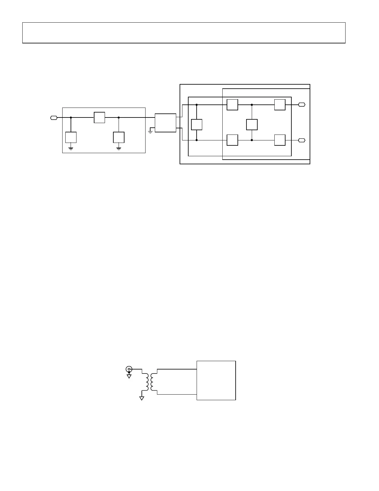
BOT
TOM SIDE
ALTERNATIVE,
LOWER-BANDS
BALUN FOOTPRINT
HIGHER-BANDS BALUN
FOOTPRINT
SINGLE-ENDED
PI NETWORK
RESISTOR/OPTIONAL AC
COUPLING CAPACITOR
SWITCHING NETWORK
DIFFERENTIAL
PI NETWORK
TOP SIDE
24159-199
Figure 228. Transmitter Matching Network on ADRV9001 Evaluation Board
Transmitter Bias and Port Interface
This section considers the dc biasing of the ADRV9001 transmitter (Tx) outputs and how to interface to each Tx port. At full output
power, each differential output side draws approximately 100mA of DC bias current. The Tx outputs are dc biased to a 1.8 V supply
voltage using either RF chokes (wire-wound inductors) or a transformer (balun) center tap connection.
Careful design of the DC bias network is required to ensure optimal RF performance levels. When designing the dc bias network, select
components with low dc resistance (RDCR) to minimize the voltage drop across the series parasitic resistance element with either of the
dc bias schemes suggested in Figure 228 and Figure 229. The red resistors (R_DCR) indicate the parasitic elements. As the impedance of
the parasitic increase, the voltage drop (ΔV) across the parasitic element increases which causes the transmitter RF performance (i.e
PO,1dB, PO,MAX, etc…) to degrade. The choke inductance (L_c) should be selected high enough relative to the load impedance such
that it does not degrade the output power. If chokes are used they should be very well matched (including PCB traces). Uneven matching
of chokes design can cause unwanted emission of spikes at the Tx output. This emission can affect components connected to the Tx
output.
The recommended dc bias network is the one using the center tap balun is shown in Figure 229. This network has fewer parasitic and
fewer total components.