UG-1828 Preliminary Technical Data
Rev. PrB | Page 166 of 277
Rx Programmable FIR Filter
Rx Programmable FIR Filter in rxnbdem is multi-functional and customizable. This module can be bypassed.
The Rx Programmable FIR supports up to 128 taps. Each tap is 24 bits width with the signed bit included. 4 sets of customized FIR
profiles can be stored at the initialization phase. One of the 4 stored FIR profiles can be switched to be loaded on the fly under the control
of the BBIC.
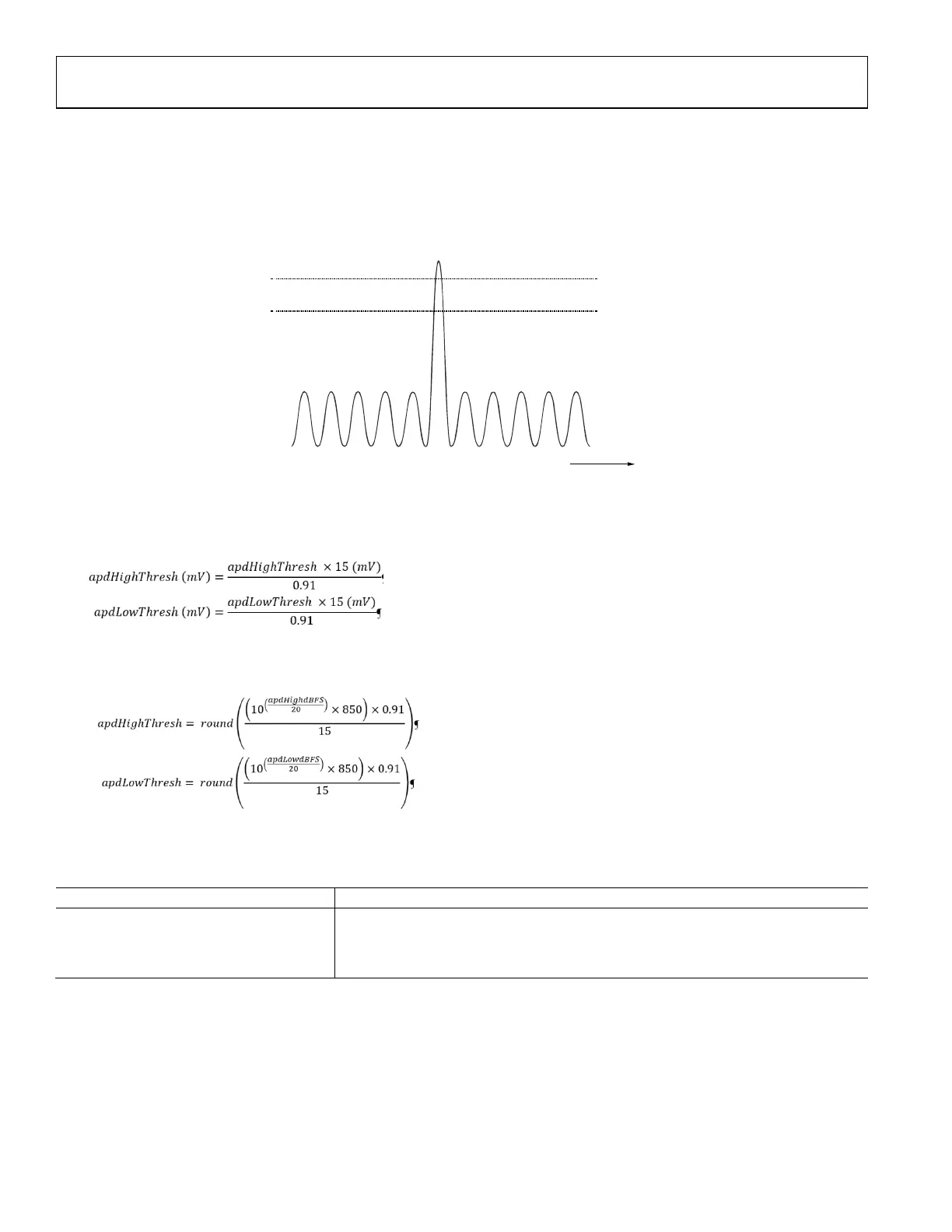
The Rx programmable FIR can be loaded a customized lowpass filter profile to stop the adjacent channel interference, which is helpful to
achieve better channel selectivity. For example: as shown in Figure 155, before the CFO is corrected, the BBIC may program a loose filter
profile onto the Rx Programmable FIR to perform common filtering. However, after the CFO is corrected via Carrier Frequency
Corrector block, a tight filter profile can be loaded to perform the deep channel selection filtering. The change in the filter profile can be
initiated by the BBIC on demand in the RF_Enabled State.
CFO
THE WANTED CHANNEL
BEFORE CFOIS CORRECTED.
THE WANTED CHANNEL
AFTER CFO IS CORRECTED.
DC
DC
LOOSE FILTER PROFILE TIGHT FILTER PROFILE
24159-129
Figure 156. Loose Filter Profile vs. Tight Filter Profile
Frequency Discriminator
Frequency Discriminator in rxnbdem is to translate the IQ signal into Frequency Deviation (FD) signal, performing the frequency
demodulation in the digital domain. This module can be bypassed.
D
D
I
Q
–
ATAN2
FREQUENCY
DEVIATION
(FD)
SQUARED
MAGNITUDE
(Mag2)
X
Y
24159-130
Figure 157. Functional Diagram of Frequency Discriminator
Illustrated by Figure 156, the Frequency Discriminator outputs the transient frequency deviation (FD) and the transient squared
magnitude (Mag2) sample by sample. The output FD and the output Mag2 are defined as followed:
where
is same as the function in Octave, and D is the programmable delay. Typically, D is chosen as ‘1’, which means 1 sampling
clock delay.
Assuming the input IQ signal is the complex single tone, given by
 Loading...