UG-1828 Preliminary Technical Data
Rev. PrB | Page 68 of 277
Guard Time Between TX_ENABLE Falling Edge and TX_ENABLE Rising Edge
The guard time between TX_ENABLE falling edge and TX_ENABLE rising edge is for making sure that the interface is turned off at the
end of the previous frame before it turns on again for the next frame. In addition, it must also make sure that the analog front end has
been powered off in the previous frame prior to powering up again in the new frame. Because it takes t
TxEnaHold
to turn off the transmit
interface after the TX_ENABLE falling edge, the next TX_ENABLE rising edge must come after a delay of at least t
TxEnaHold
. This ensures
that the interface is turned off at the end of the previous frame before it turns on again for the next frame. Since it takes t
TxEnaFall2Off
to
power down the transmitter analog front end after the TX_ENABLE falling edge, the next TX_ENABLE rising edge must come after a
delay of at least equal to t
TxEnaFall2Off
− t
TxEnaRise2AnaOn
. This ensures that the analog front end has been powered off in the previous frame prior
to powering up again in the new frame. If the timing parameters are set appropriately, these two conditions are almost identical. If they
are not identical for some reason, the guard time should be set as the maximum of t
TxEnaHold
and t
TxEnaFall2Off
− t
TxEnaRise2AnaOn
. Figure 59
describes this scenario.
Tx_ENABLE
MAX (t
TxEnaHold
, t
TxEnaFall2Off
– t
TxEnaRise2On
)
24159-060
Figure 59. Minimum Guard Time Between TX_ENABLE Falling Edge and TX_ENABLE Rising Edge
Guard Time Between RX_ENABLE Falling Edge and RX_ENABLE Rising Edge
The guard time between the RX_ENABLE falling edge and RX_ENABLE rising edge is for making sure that the interface is turned off at
the end of the previous frame before it turns on again for the next frame. Because it takes t
RxEnaHold
to turn off the receive interface after the
RX_ENABLE falling edge, the next RX_ENABLE rising edge must come after a delay of at least t
RxEnaHold
. This ensures that the interface is
turned off at the end of the previous frame before it turns on again for the next frame. Because the analog powers down before the
interface, the analog front end is guaranteed to power down prior to being powered up at the start of the next frame if this condition is
met. Figure 60 describes this scenario.
Rx_ENABLE
t
RxEnaHold
24159-061
Figure 60. Minimum Guard Time Between RX_ENABLE Falling Edge and RX_ENABLE Rising Edge
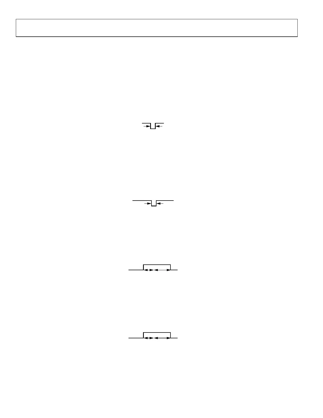
Hold Time Between TX_ENABLE Rising Edge and TX_ENABLE Falling Edge
After a TX_ENABLE rising edge, its falling edge must come after a delay of at least t
TxEnaRise2AnaOn
or t
TxEnaRise2On
(if controlling antenna
switch). In order to actually transmit, the channel must be on for a duration longer than its propagation delay. This can be achieved,
either by making sure TX_ENABLE is high for longer than the propagation delay, or by ensuring the t
TxEnaHold
and t
TxEnaFall2Off
are longer
than t
TxPD
. Figure 61 describes this scenario.
Figure 61. Minimum Hold Time between TX_ENABLE Rising Edge and TX_ENABLE Falling Edge
Hold Time Between RX_ENABLE Rising Edge and RX_ENABLE Falling Edge
After a RX_ENABLE rising edge, its falling edge must come after a delay of at least t
RxEnaRise2AnaOn
or t
RxEnaRise2On
(if controlling LNA power).
In order to actually receive data, the channel must be on for a duration longer than its propagation delay. This can be achieved, either by
making sure RX_ENABLE is high for longer than the propagation delay or by ensuring the t
RxEnaHold
is longer than t
RxPD
. Figure 62
describes this scenario.
Rx_ENABLE
t
RxPD
t
RxEnaRise2On
24159-063
Figure 62. Minimum Hold Time Between RX_ENABLE Rising Edge and RX_ENABLE Falling Edge
Timing Parameters with Power Savings Modes
ADRV9001 offers several channel power savings modes (Power Saving Mode 0, Power Saving Mode 1, and Power Saving Mode 2) that
trade off better power savings with longer transition time to turn on and turn off a transmit or receive channel. Please refer to the Power
Saving and Monitor Mode section in this User Guide for more details about power saving modes. In order to take advantage of these
power saving modes, the timing parameters must be set appropriately.
 Loading...