UG-1828 Preliminary Technical Data
Rev. PrB | Page 88 of 277
The transition period is, at a minimum, the time required to setup the Rx or Tx channel and switch to a new operating frequency (first
portion of transition time in Figure 86). However, it can be whatever length the user decides for their framing requirements (second
portion of transition time in Figure 86).
The dwell period is the ‘on air’ time, where a channel is in RF enabled state. The dwell period can be any length of time the user requires
to operate on a frequency.
HOP signal marks the beginning and the end of a Transmit or a Receive frame. The HOP signal is triggered by a DGPIO pin, which can
be assigned from any of the available DGPIO pins. Each edge of the HOP signal marks both the possible start and end of a hop frame.
Channel Setup Signal
24159-484
HOP SIGNAL
CHANNEL SETUP
CHANNEL RF
ENABLED
HOP FRAME 0 HOP FRAME 1
Figure 87. Channel Setup Signal
The channel enable pins (namely Tx/Rx_ENABLE pins), used in non-FH operation, are repurposed in frequency hopping to signal if an
upcoming HOP frame is operating on an Rx or Tx channel. These pins are redefined as Rx/Tx setup; however, they are the same
dedicated channel enable hardware pins, which are used to enable an Rx or Tx channel in non-frequency hopping mode.
As seen in Figure 87, the channel setup is used to signal a channel is enabled one frame in advance. For example, the channel setup signal
is high prior to the start of Hop Frame 0, but that channel is not enabled until Hop Frame 1.
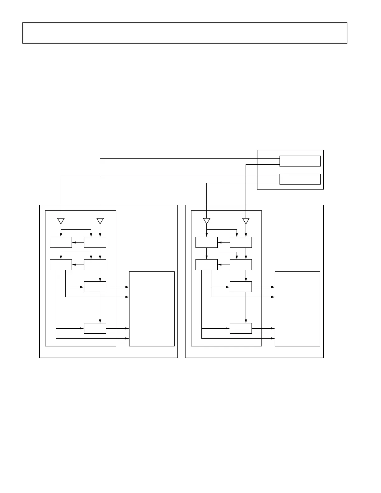
The frequency information comes from the BBIC. Before each Tx or Rx setup, we expect to get some message (this may come in various
forms which is discussed in later sections) which indicates a frequency. Prior to each hop, the channel (Tx or Rx) information and the
frequency information are obtained.
Note Tx setup signal falling edge has special meaning, it indicates the start of the interface. At this point, Tx data starts transmitting at
the interface. More information on this will be shown in sections.
MODES OF OPERATION
ADRV9001 allows the user to achieve various framing requirements by providing three modes of operation.
Table 34. Frequency Hopping Modes of Operation
Mode Transition Time
Total frame duration
(transition + dwell) PLLs
PLL Return
Time
PLL Cal
Mode Channel
LO mux with hop table
preprocess
< channel setup +
lo retune
> 20 µs (Rx)
> 30 µs (Tx)
2 LOs
2 transitions + 1
dwell
Fast Cal
mode
Single (1T1R)
LO mux with hop table
real time update
< channel setup +
lo retune
> 40 µs (Rx)
> 50 µs (Tx)
2 LOs
1 transitions +
sub 1 dwell
Fast Cal
mode
Single/Dual (1T1R or
2T2R diversity)
LO retune with hop
table real time update
> channel setup +
lo retune
> 40 µs (Rx)
> 50 µs (Tx)
1 LO Sub 1 transitions
Fast Cal
mode
Single/Dual (1T1R or
2T2R diversity)
Currently, all modes of frequency hopping operation within ADRV9001 use a fast PLL calibration. The modes are differentiated by the
user’s transition time and dwell time requirements. ADRV9001 defines two modes of PLL usage: LO Muxing and LO Retune.
Note there are two modes of PLL calibration, one is fast one is normal. Fast mode takes less time and normal mode has better
performance but takes more time. The PLL calibration mode can be set with adi_adrv9001_PllCalibration structure.
LO Muxing
For short transition times, ADRV9001 requires two LOs to be used in a ping pong operation. This means while one PLL is used for one
frame, the other PLL is being retuned for the next frame. During the transition time, the LOs are swapped.
LO Retune
For longer transition times, the PLL can be retuned for the starting frame within the transition time, if that time is greater than the sum
of the PLL lock time and channel bring up time.
 Loading...