UG-1828 Preliminary Technical Data
Rev. PrB | Page 216 of 277
0
5.0
–5.0
2.0
1.0
–1.0
–2.0
0.5
–0.5
0.2
–0.2
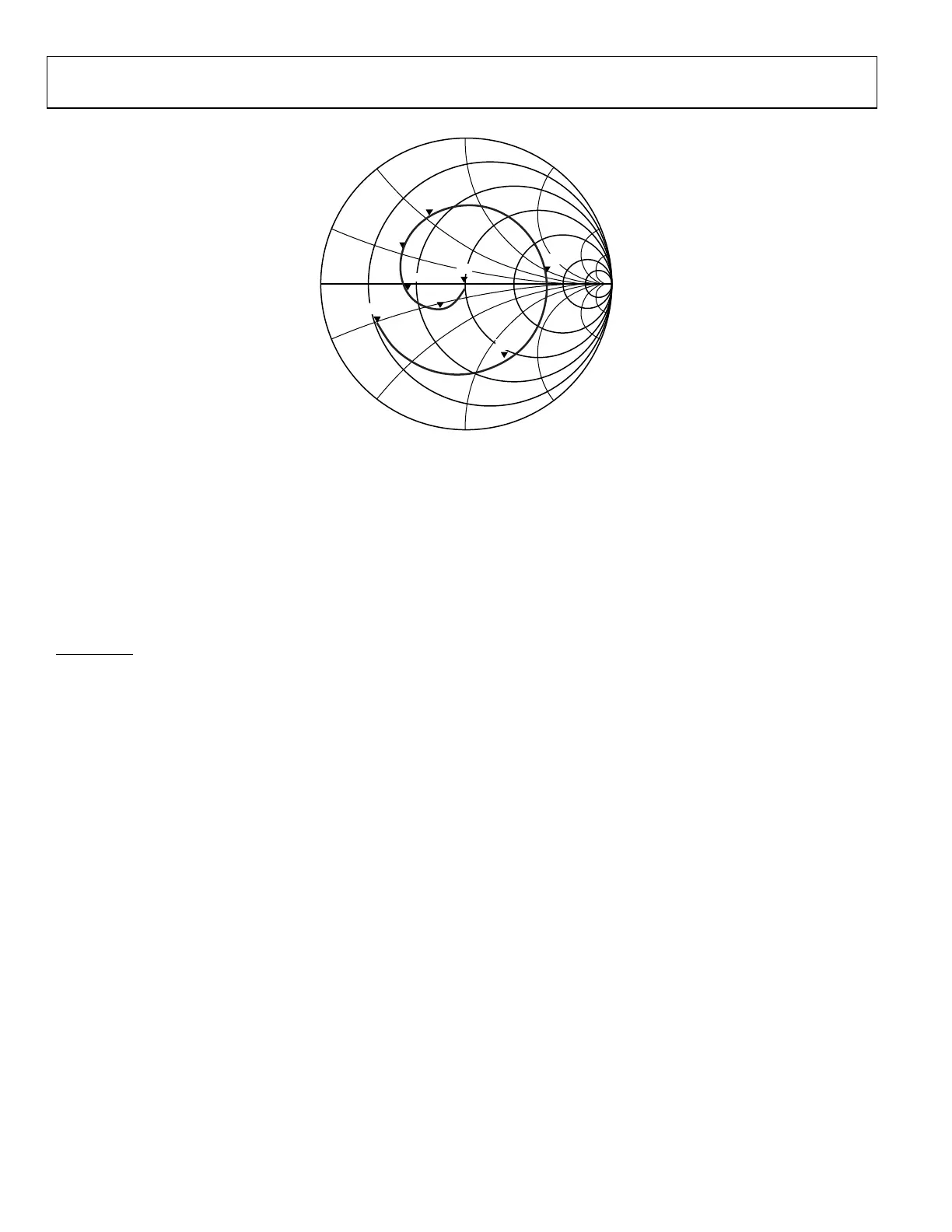
m1
FREQUENCY = 60.00MHz
S(10,10) = 0.039/–81.146
IMPEDANCE = 100.912 – j7.872
m2
FREQUENCY = 1.000GHz
S(10,10) = 0.254/–135.783
IMPEDANCE = 65.484 – j24.798
m3
FREQUENCY = 2.000GHz
S(10,10) = 0.415/–173.750
IMPEDANCE = 41.462 – j4.523
m8
FREQUENCY = 12.000GHz
S(10,10) = 0.668/–157.623
IMPEDANCE = 20.688 – j18.963
m7
FREQUENCY = 9.000GHz
S(10,10) = 0.593/–64.388
IMPEDANCE = 77.231 – j127.520
m6
FREQUENCY = 7.000GHz
S(10,10) = 0.546/9.880
IMPEDANCE = 315.757 – j84.329
m4
FREQUENCY = 3.000GHz
S(10,10) = 0.496/151.568
IMPEDANCE = 35.627 + j22.290
m5
FREQUENCY = 4.500GHz
S(10,10) = 0.535/101.068
IMPEDANCE = 47.846 – j70.402
FREQUENCY (60.00MHz TO 12.00GHz)
S(10, 10)
M6
M7
M8
M5
M3
M2
M1
M4
24159-182
Figure 210. External LO Series Equivalent Differential Input Impedance
Care should be taken when selecting an on-board balun for this application. Combination of amplitude and phase balance performance
of the balun can affect quadrature error performance. Additionally, duty cycle and differential second order harmonic distortion impacts
the ability of to correct quadrature error. The recommended minimum requirement for Ext LO input pins is a combination of no more
than 5 degree differential phase error, 1dB differential amplitude error, 2% duty cycle error, and less than −50 dBc even order
harmonics(primarily 2nd order).
The ADRV9001 provides special mode of operation for external LO in range from 500 MHz to 1000 MHz. In that region it is possible to
inject external LO that will produce RF Channel frequency with x1 multiplier.
For example:
For FEXTLO = 500 MHz the FCHANNEL = 500 MHz
For FEXTLO = 1000 MHz, the FCHANNEL = 1000 MHz
 Loading...