UG-1828 Preliminary Technical Data
Rev. PrB | Page 184 of 277
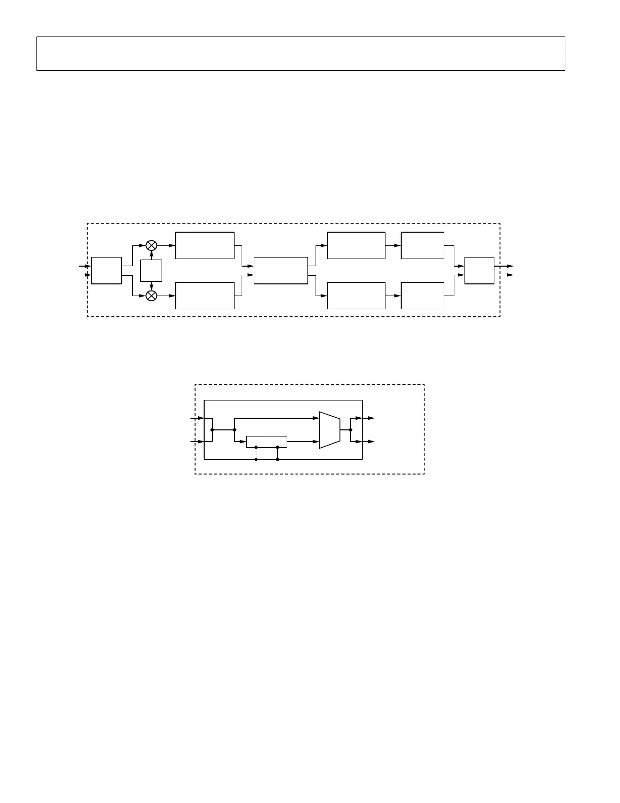
The user could configure the changeModelTapOrders and modelOrdersForEachTap through TES, as shown in Figure 176 and Figure 177.
shows the default model tap configuration and Figure 176 shows a customized model tap configuration which is equivalent to B[0] = 0x07,
B[1] = 0x7F, B[2] = 0x07 and B[3] = 0x06. (Note Tap 0 and Tap 2 should always be the same. For simplicity GUI uses X to represent
)
Figure 177. Configuring Default Model Tap Order Through TES
Figure 178. Configuring Customized Model Tap Order Through TES
preLutScale
This value, given as a fixed point U2.1 number, sets the scaling factor before searching the LUT. The scaling factor can be set as 1, 1.5, 2,
2.5, 3 and 3.5. This allows the user to scale the input signal magnitude in order to cover close to the full range of the LUT for better DPD
performance. If the signal input to the compander is too small, then only part of the LUT is used. When the input signal is small, user
could try different scaling factors to increase the signal level which might improve the DPD performance. The scaling factor can be
determined according to the dBFS of the input data peak. As an example, if the signal peak power is less than −4 dBFS, the scaling factor
3.5 could be applied. As shown in Figure 176 and Figure 177, the default value of “pre-LUT Scale” is 2, which could be further changed
by user.
DPD Post Initial Calibration Parameters Configuration
The second set of DPD parameters should be configured after initial calibration. It is defined by the following data structure:
typedef struct adi_adrv9001_DpdCfg
{
uint32_t numberOfSamples;
bool outlierRemovalEnable;
uint32_t outlierRemovalThreshold;
uint32_t additionalPowerScale;
uint32_t rxTxNormalizationLowerThreshold;
uint32_t rxTxNormalizationUpperThreshold;
bool immediateLutSwitching;
bool useSpecialFrame;
bool resetLuts;
} adi_adrv9001_DpdCfg_t;
Table 80 briefly summarizes all the DPD post initial calibration parameters described in the data structure.
 Loading...