UG-1828 Preliminary Technical Data
Rev. PrB | Page 134 of 277
Bits Corresponding Enum Calibration Description
D23 ADI_ADRV9001_TRACKING_CAL_RX_RSSI
Rx RSSI
Tracking
Calibration
This is used to enable/disable Rx signal strength
measurement on-the-fly. Currently this tracking
calibration in not available.
External System Requirements for Tracking Calibrations
Different from initial calibrations, tracking calibrations are performed on-the-fly with real-time traffic data. Therefore, it is mostly
transparent to the users and fully controlled by the internal micro-processor. The external system requirements for users are as the
following:
• Make sure external paths are available when running some tracking calibrations on external loopback paths.
• When external loopback path after power amplifier is used (ELB2), a suitable attenuator must be chosen between the power
amplifier output and the observation channel input to prevent transmitter output data from saturating the observation channel
input.
• When external DPD is employed in the system, it should time share with other transmitter tracking calibrations to avoid conflicts.
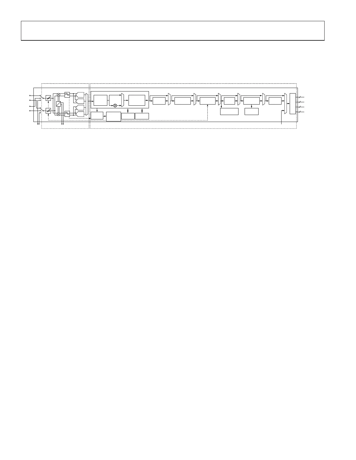
For tracking calibrations, the TES provides the option to enable or disable those calibrations as shown in Figure 132. Note in the current
release, the configurable transmitter tracking calibrations are digital pre-distortion (TX_DPD), LO Leakage (TX_LO_LEAKAGE) and
QEC (TX_QEC). When “Tx Direct FM/FSK” mode is selected in DMR or AnalogFM profiles, TX_LO_LEAKAGE and TX_QEC
calibrations are not applicable. Those options become unconfigurable in TES. The configurable receiver tracking calibrations are
automatic gain control (RX_AGC), baseband DC offset (RX_BBDC), (2nd order) harmonic distortion (RX_HD2), frequency
independent QEC (RX_QEC_FIC) and frequency dependent QEC for WB (RX_QEC_WBPOLY).
The tracking calibrations can be enabled or disabled on-the-fly when the device is operational.
Figure 132. Tracking Tx/Rx Calibration Configuration Through TES
 Loading...