Preliminary Technical Data UG-1828
Rev. PrC | Page 321 of 338
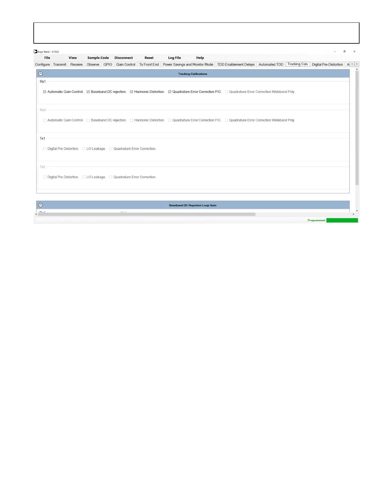
Figure 307. Tracking Calibration Tab
Digital Predistortion
For more detailed information on DPD, see the Digital Predistortion section for more details. This tab also contains the Closed-Loop
Gain Control (CLGC) settings. This uses the same processing engine as the DPD and is used to keep the gain from the output of the PA at
a constant level.
To use the CLGC use it in open-loop configuration at first and read the ‘CLGC Last Gain’ and ‘CLGC Filtered Gain’ from the Transmit
tab. The user then inputs these readings into the CLGC Gain Target and CLGC Filter Alpha fields in the Digital Pre-Distortion tab and
closes the loop by unchecking the open-loop tick box. The Tx output power can be controlled by the CLGC Target Gain (dB) field in the
transmit tab.
To use either of these functions the DPD tracking calibration needs to be turned on, the two functions use the same tracking engine.
TDD Enablement Delays
For more detailed information on TDD enablement delays, see the Timing Parameters Control section for more details.
Auxiliary DAC/ADC
ADRV9001 evaluation software allows user for setting Auxiliary ADC/DAC for different control or monitoring purposes. User can go to
Auxiliary tab and enable Aux DAC/ADC here. For Aux DACs, user must specify a DAC code, valued from 0 ~ 4095. This effectively sets
the voltage level for that Aux DAC pin. For Aux ADCs, user can press Capture Again to observe the one time voltage value on the Aux
DAC pin.
 Loading...