Preliminary Technical Data UG-1828
Rev. PrB | Page 65 of 277
USER PROVIDES NAVASSA
ADRV9001 PROVIDES USER
HELPER PARAMETERS
RX_INTERFACE
FRAMING ON AIR
FRAMING AT BBIC
PIN: RX_ENABLE
RX ON: LNA POWER OUT
RX ANALOG POWER
t
RxPD
t
RxPD
t
RxGT
t
RxPD
t
RxGT
24159-057
t
RxEnaHold
t
RxEnaFall2Off
RX
RX
VALID DATA
t
RxEnaRise2On
t
RxPD
t
RxEnaSetup
t
RxEnaRise2AnaOn
t
RxPD
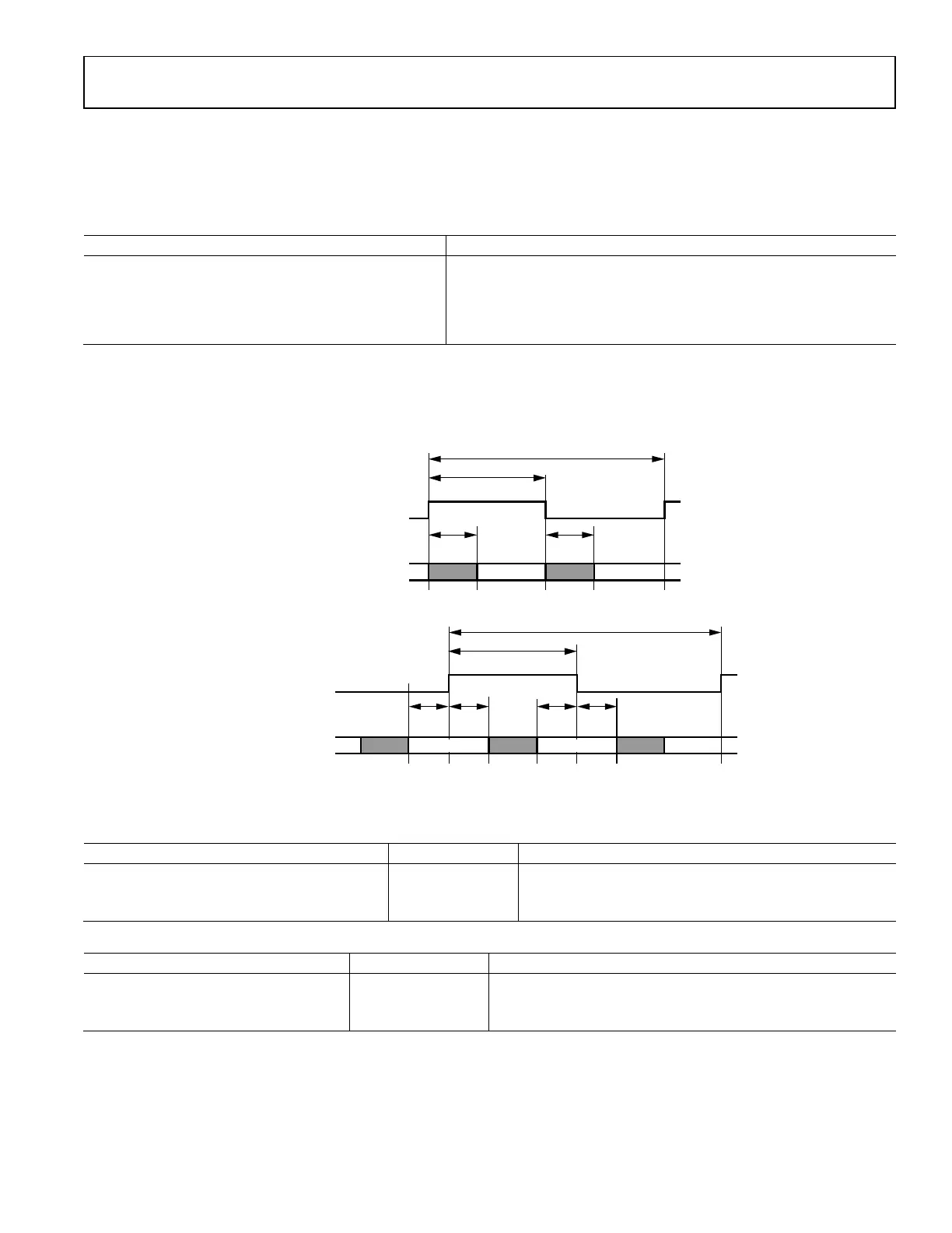
Figure 56. Receive Timing Parameters
As shown in Figure 56, similarly, a receive burst is composed of a series of valid receive data with user’s option of padding guard data at
the beginning and end of the valid data. Similar to transmit, based on the timing parameters configured by the user, it is the user’s
decision if full or partial of the guard data should be received and it is the user’s responsibility to make sure that the guard data usage is
compliant with the standard requirement. The RX_ENABLE pin is controlled by the user to signal ADRV9001 the start and end of a
receive burst at the air (Note RX_ENABLE should rise before the start of the receive burst at air to allow powering up analog front end.).
Based on the RX_ENABLE signal and a set of receive timing parameters configured by the user, ADRV9001 further controls receive
analog components, receive interface, and the external LNA (if it is controlled by ADRV9001 instead of user) to make sure that the
received burst is sent to BBIC at the deterministic time as desired by user.
Similar to transmit timing parameters, as shown in Figure 56, receive timing parameters can be categorized into three types: ADRV9001
parameter (ADRV9001 provides to user), user parameter (user provides to ADRV9001) and helper parameters (determined by user
which are not needed to provide to ADRV9001 but could be used by the user to derive other required timing parameters).
All the parameters used in Figure 56 are explained further in Table 23. All bounds specified in Table 23 are suggestions for optimal
operation, no hardware or software restrictions prevent a customer from setting values that are out of bounds. The maximum
programmable parameter value is specified in later sections.
Table 23. Receive Timing Parameters Description
Delay Description
Provided
By
Bounds Comments
enableSetupDelay
(t
RxEnaSetup
)
Time taken for ADRV9001
to power up Rx analog
front end. This may or may
not include PLL tuning
time based on the use
case. (For example, when
Tx and Rx shares the same
LO but at different
frequency, PLL tuning is
needed at the frame
boundary.).
ADRV9001
Parameter
Min: N/A
Max: N/A
No PLL tuning @ frame boundary:
8 μs (analog power-up time)
PLL tuning @frame boundary:
758 μs (Analog Power-Up Time +
PLL Tuning Time)
(The PLL tuning time 750 μs refers
to the case when internal LO is
used. When external LO is used,
users should calculate and use their
own PLL tuning time. Note the time
required for PLL tuning is
continuously improving in the
future.).