Preliminary Technical Data UG-1828
Rev. PrB | Page 217 of 277
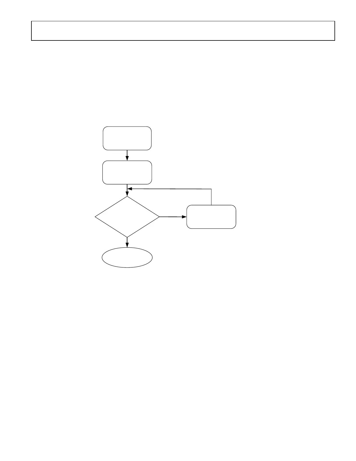
Figure 211. External LO Impedance Matching Network
Table 96. EXTLO1± and EXTLO2± Impedance Matching Network
L324
C349
L325
L326
C319
R356
R321
C357
C362/363
C364/366
L330/332
C320/321
L331
L333/335
C322/323
L334
R350
60 MHz – 6
GHz
MiniCircuit
s
TCM1-
83X+
L324:
DNI
C317:
DNI
L325:
0.33nH
( AVX
L0201)
C349: DNI
R318: DNI
L326:
DNI
C319:
DNI
R356:
DNI
R321:
DNI
R319:
0 Ω
C357:
DNI
R357:
DNI
C362/363:
DNI
R326/327:
DNI
R328/329:
DNI
C364/366:
470 pF
(Murata
GRM03)
L330/332:
0.82 nH
( AVX L0201
)
C320/321:
DNI
R310/354:
DNI
L331:
DNI
C352:
0.3 pF
(Murata
GJM03)
L333/335:
1.2 nH
( AVX L0201
)
C322/323:
DNI
R311/355:
DNI
L334: DNI
C353: 0.3
pF
(Murata
GJM03)
R350:
DNI
C373:
DNI
6 GHz – 12
GHz
MiniCircuit
s
NCR2-123+
L324:
DNI
C317:
DNI
L325:
DNI
C349: DNI
R318:
0 Ω
L326:
DNI
C319:
DNI
R356:
DNI
R321: 0
Ω
R319:
DNI
C357:
DNI
R357:
DNI
C362/363:
: 470 pF
(Murata
GRM03)
R326/327:
DNI
R328/329:
DNI
C364/366DN
I
L330/332:
DNI
C320/321:
DNI
R310/354: 0
Ω
L331:
DNI
C352:
DNI
L333/335:
DNI
C322/323:
DNI
R311/355: 0
Ω
L334: DNI
C353: DNI
R350:
DNI
C373:
DNI
A single-ended external LO signal can be applied by bypassing balun interface and installing appropriate impedance matching network
comprised of L324/C317, C349/L325/R318, and L326/C319 and AC-coupling cap of C357. Additionally, a large cap for C373 should be
installed to provide an ac-ground for the negative side of input pins to internal buffer circuitry.
EXTERNAL LO IMPEDANCE MATCH MEASUREMENT DATA
External RF Port Impedance Match Measurement Data for 60 MHz to 6 GHz Band Match
Return loss was measured on EXT LO RF ports of eval boards and plotted on Figure 211; blue and pink curves represent three different
return loss measurements and black dotted line represents simulated return loss curve. Simulated Insertion loss including balun loss is
plotted on Figure 212.
 Loading...