Preliminary Technical Data UG-1828
Rev. PrB | Page 91 of 277
• The ADRV9001 expects that the lower DPGIO number is the LSB of the index.
• Adjacent DGPIO pins must be assigned (for example, cannot assign DGPIO-0 to Bit 0, and DPGIO-11 to Bit 1, and so on).
• The ADRV9001 samples the DPGIO pins at every channel setup rising edge. It will use any index if the sampled index is deemed
valid (meaning, provide a valid index to the frequency hopping table).
Switching Between Two Frequency Hopping Tables
In any frequency hopping mode, ADRV9001 allows the user to switch between either of the frequency hopping tables.
• When a table is switched, the index to the new table is set to 0.
• The new table is read at the next channel setup rising edge.
Automatic Table Ping Pong
Automatic ping pong mode works similarly to regular automatic increment mode. However, once the end of one table has been reached,
ADRV9001 will automatically switch to the other table. In this way, the user could continuously increment through, at most, 128 table
entries/hop frequencies.
Unlike the manual switch, this mode does not require any external signal from the user. ADRV9001 will handle the switching between
the two tables automatically.
Automatic Table with Manual Switch
The user can switch between the two frequency hopping tables at any time using an API or by a DGPIO pin.
The DGPIO pin for hop table switch can be configured at initialization.
When the hop table select pin is low, frequency hopping table A is set as the active table, when the hop table select pin is set high,
frequency hopping table B is set as the active table.
The falling or rising edge signals to ADRV9001 to switch to the A or B table, respectively.
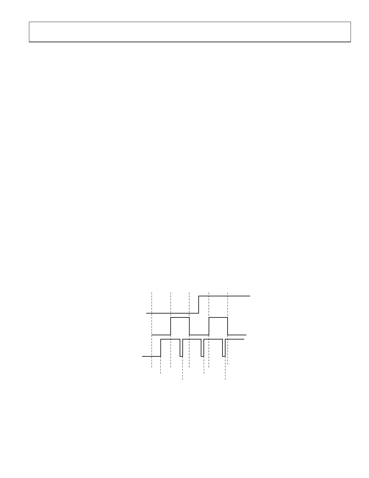
As per Figure 90¸the first channel setup rising edge, after the hop table switch, reads from the newly selected table.
In the example from Figure 90, the new information read from the table will appear on air at frame 4.
Like the PIN method, the user can issue an API to switch between the two tables.
HOP table select pin is sampled at the channel setup rising edge. User must set HOP table select pin prior to the upcoming channel setup
rising edge. ADRV9001 resets the frequency hopping table index to zero upon switch. In other words, when the user switches between
tables, the new table always starts at entry 0.
1 2 3 40
HOP TABLE
SELECT PIN
HOP
SIGNAL
CHANNEL
SETUP
SIGNAL
24159-487
READ HOP
TABLE A
ENTRY 0
READ HOP
TABLE A
ENTRY 1
READ HOP
TABLE B
ENTRY 1
READ HOP
TABLE B
ENTRY 0
Figure 90. Manual Table Switch
Index by Pin with Manual Switch
Like the automatic increment mode, the user can use a DGPIO pin or API to switch between tables which indexing the table by pin.
ADRV9001 cannot automatically ping pong between tables when the user is in index by pin mode.