Preliminary Technical Data UG-1828
Rev. PrB | Page 89 of 277
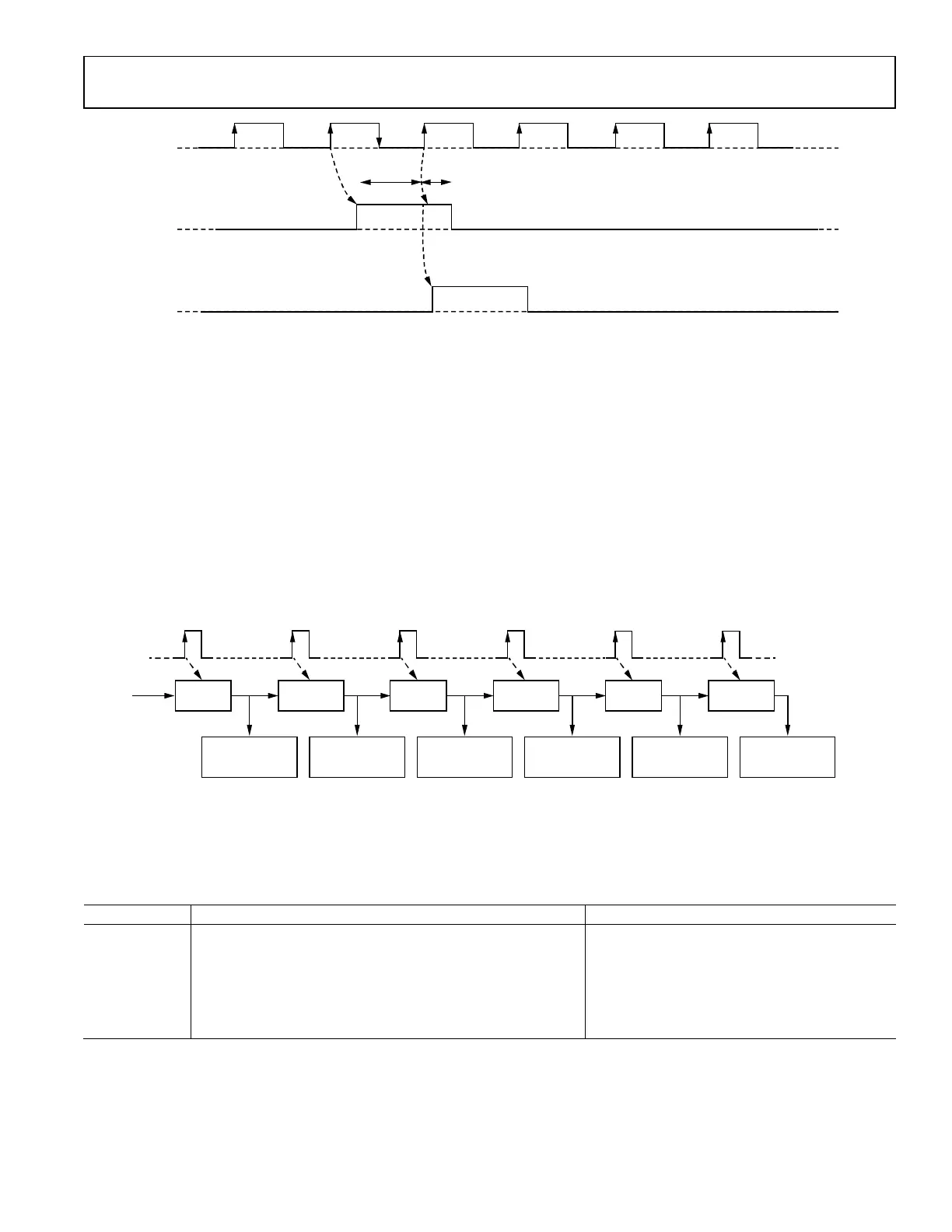
Pre-Process Mode vs. Real-Time Process Mode
Pre-process Mode refers to the frequency hopping tables being sent to ADRV9001 and processed before frequency hopping operation
begins.
Real-time Process Mode refers to the frequency hopping table not being processed at initialization stage but at the hopping stage. At
each hop, the next entry in the table is read and processed. This allows the user to update the frequency hopping tables on the fly. These
two modes of operations are referring to the frequency hopping tables, and they will be explained in further detail in the frequency
hopping table sections
CHANNEL AND PROFILE SELECTION
Depending on the operation mode, operations of dual channel (2T2R, 2T, or 2R) diversity, or single channel (1T1R, 1T, or 1R) is
supported.
Table 35. Channel Selection
Channel Use
Case
Profile Propagation Delay Requirements
Number of
Channels
Selectable Mode
TRx
Propagation delay must be less than the duration of a single hop
frame.
1T1R All modes
2T2R
LO mux with hop table
real time update
LO retune with hop table
real time update
Rx
Propagation delay can be greater than the duration of a hop
frame.
1R All modes
2R
LO mux with hop table
real time update
LO retune with hop table
real time update
Tx
Propagation delay can be greater than the duration of a hop
frame.
1T All modes
2T
LO mux with hop table
real time update
LO retune with hop table
real time update
FREQUENCY HOPPING OPERATION RANGES
Operation Ranges
• The full Rx gain range available in regular mode is supported in frequency hopping mode.
• The full Tx attenuation range available in regular mode is support in frequency hopping mode.
FREQUENCY HOPPING TABLE
Hopping Table Definition and Entries
All modes of frequency hopping require the use of a frequency hopping table. A frequency hopping table is a list of frequency and other
operational parameters for each hop frame. At initialization, the user will provide ADRV9001 a frequency hopping table, as well as the
number of entries, or frequencies, within that table.
ADRV9001 supports the loading of two tables (table A and table B), each with a minimum length of 1, and a maximum length of 64
entries. (a total of 128 hop entries/frequencies, if two tables are loaded).
An entry in the frequency hopping table is defined as follows.
Table 36. Hop Table Entry
Parameter Descriptions
hopFrequencyHz Operating frequency, in Hz.
rxOffsetFrequencyHz The intermediate frequency, if a frame is Rx.
rxGainIndex Starting gain index, if frame is Rx.
TxAttenuation_mdB Starting attenuation level, in mdB, if frame is Tx.
The channel(s) which will be enabled each hop frame is not known at initialization. During frequency hopping operation, the user will
use the channel setup signals to inform ADRV9001 on which channel to enable. Therefore, each entry in the hop table contains
parameters for both Rx and Tx and it processes the entry appropriately, depending on whether an upcoming hop frame is operating on
Rx or Tx.