Preliminary Technical Data UG-1828
Rev. PrB | Page 167 of 277
where A is the signal magnitude, f
t
is the tone frequency, f
S
is the sampling frequency. The output of the frequency discriminator (FD) is
D × 2f
t
/f
S
while the output Mag2 is A
2
.
NB Programmable FIR
NB Programmable FIR in rxnbdem is to perform the pulse shaping filtering or the low pass filtering at the output of the Frequency
Discriminator. This module can be bypassed.
The NB Programmable FIR supports up to 128 taps. Each tap is 24 bits width including the sign-bit, and only 1 set of customized FIR
profiles can be loaded.
Resampler
Resampler in rxnbdem adjusts the sampling phase of the IQ signal or that of the FD signal. This module can be bypassed.
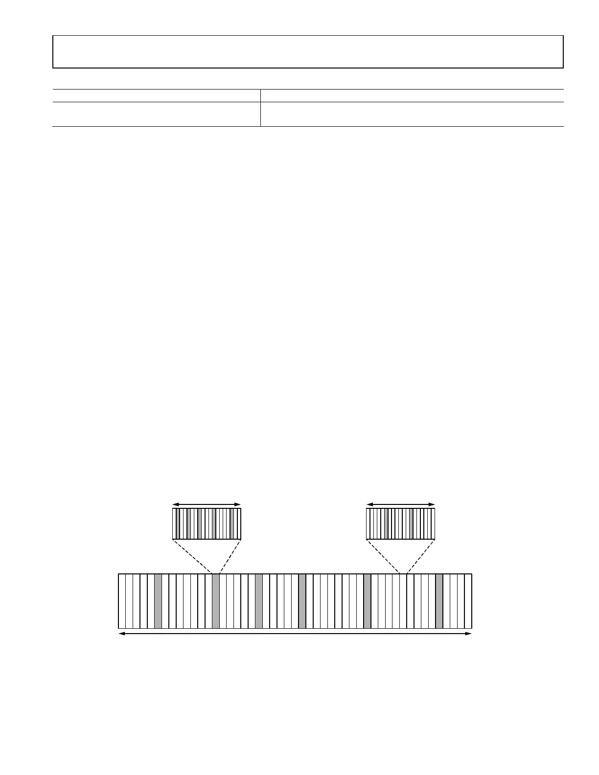
Figure 157 illustrates the functional diagram of the Resampler, the Resampler resamples the incoming received signal, by reconstructing
intermediate samples between every 2 inputs samples according to the re-sample phase parameter,
.
In the frequency domain, the ideal digital Resampler has the transfer function as below:
where B
x
is the maximum bandwidth of the input signal. Filtered by the ideal resampling filter, the input signal, x(kT
S
), is converted to
the output signal y(kT
S
) = x((k + μ) × T
S
)
SUB-FIR3 SUB-FIR2
SUB-FIR1
SUB-FIR0
µ
16: S1.15
I, Q
I, Q
24159-131
Figure 158. Functional diagram of the Resampler
Scanning the sampling phase μ from 0 to 0.5, the maximum magnitude difference of the frequency transfer function between the
Resampler and the ideal digital resampler is collected and plotted at the upside of Figure158. The maximum phase error is collected and
plotted at the downside of Figure 158.
The Resampler can be used in both the wideband and narrowband modes.
50
40
30
20
10
0
0.5
0.4
0.3
0.2
0.1
0
MAX MAGNITUDE ERROR (dB)MAX PHASE ERROR (Sample)
0 0.1 0.2 0.3 0.4 0.5 0.6 0.7 0.8 0.9 1.0
NORMALIZED FREQUENCY (×
Rad/Sample)
0 0.1 0.2 0.3 0.4 0.5 0.6 0.7 0.8 0.9 1.0
NORMALIZED FREQUENCY (×
Rad/Sample)
MAX MAGNITUDE ERROR FOR µ = [0:0.001:0.5]
MAX PHASE ERROR FOR µ = [0:0.001:0.5]
X = 0.9
Y = 8.558
X = 0.2
Y = 0.00081
X = 0.4
Y = 0.01989
X = 0.6
Y = 0.0407
X = 0.7
Y = 1.302
X = 0.8
Y = 3.459
X = 0.3
Y = 0.004165
X = 0.1
Y = 5.189e-05
X = 0.5
Y = 0.09938
X = 0.9
Y = 0.1648
X = 0.2
Y = 4.893e-05
X = 0.4
Y = 0.0007297
X = 0.6
Y = 0.01102
X = 0.7
Y = 0.03144
X = 0.8
Y = 0.07514
X = 0.3
Y = 0.0002133
X = 0.1
Y = 1.589e-05
X = 0.5
Y = 0.02958
24159-132
Figure 159. Maximum Magnitude/Phase Error of the Resampler
 Loading...