Preliminary Technical Data UG-1828
Rev. PrB | Page 187 of 277
externalLoopbackPathDelay
DPD requires the alignment of the transmit signal capture x(t) with the external loopback capture y(t). The externalLoopbackPathDelay
parameter provides user the capability to compensate for additional delays on the external loopback path from the ADRV9001 transmit
output to ORx input. User should measure this delay and provide it to ADRV9001 before initial calibration. The measured delay is then
used to compensate the delay between x(t) and y(t). This parameter is critical especially for wideband applications due to high sample
rate. In narrowband application, it is less critical so user could simply set it to be zero unless there is a larger than usual delay in the
external loopback path.
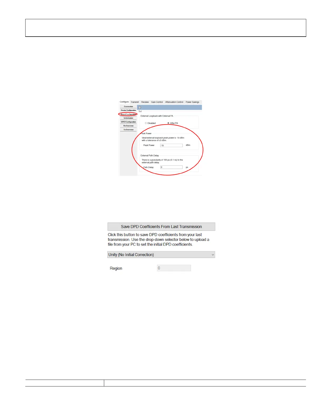
User could set these 2 configurations through TES as shown in Figure 179.
Figure 180. Configuring Board Configuration Related Parameters Through TES
SAVE AND LOAD DPD COEFFICIENTS FROM LAST TRANSMISSION
The ADRV9001 DPD also provides user an option to save and load DPD coefficients from last transmission. Therefore, DPD could
either start from scratch (unity coefficients) or a set of known coefficients. This is a very useful option if user wants to reach convergence
quickly under a similar transmit operation condition. User could utilize this feature as shown below in the TES.
Figure 181. Save and Load DPD Coefficients from Last Transmission Through TES
DPD API PROGRAMMING
A set of API commands are provided to set and inspect the DPD parameters, which is summarized in Table 81. Board configuration
parameters should be set through ADRV9001 initialization structure. Please refer to the doxygen document for more details.
Table 81. DPD APIs
DPD Rx Function Name Description
 Loading...