Preliminary Technical Data UG-1828
Rev. PrB | Page 73 of 277
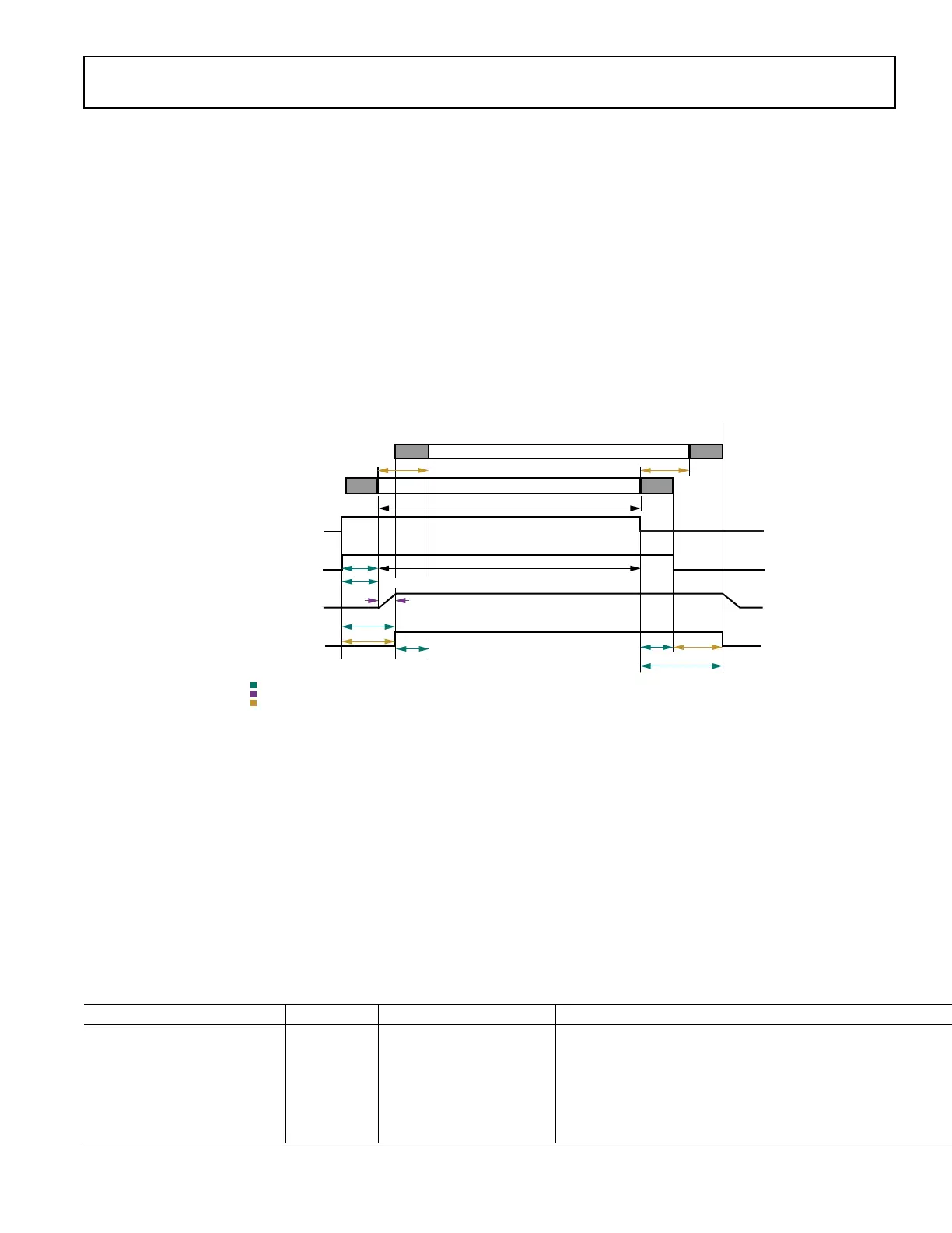
Table 26. User Provided Receiver Timing Parameters
Timing Parameter Min Value Max Value Comment
enableRiseToAnalogOnDelay
(t
RxEnaRise2AnaOn
)
Max of the following values: 0
t
PowerUpPSM
(for the maximum
intended power savings mode)
91 ms/scaleFactor Default = min
enableRiseToOnDelay
(t
RxEnaRise2On
)
enableRiseToAnalogOnDelay +
enableSetupDelay
91 ms/scaleFactor
Default = min
Not needed if not controlling LNA power.
enableGuardDelay
(t
RxGT
)
(not used currently)
0 91 ms/scaleFactor
Default = min
Can increase if performance degradation
is observed and the channel is receiving
for some time before the start of the
actual frame
(Forced to be 0 currently by ADRV9001).
enableFallToOffDelay
(t
RxEnaFall2Off
)
(Not Used Currently)
0 91 ms/scaleFactor
Default = min
Can increase if performance degradation
is observed and the channel is receiving
for some time after the end of the actual
frame. Can still be used if not controlling
LNA power down.
(Forced to be 0 currently by ADRV9001).
enableHoldDelay
(t
RxEnaHold
)
enableFallToOffDelay
enableFallToOffDelay +
propagationDelay
Default = max
Can decrease if not all data received on
air must be sent over interface.
When ADRV9001 calculates the default values, it uses the transmit/receive propagation delay internally characterized for different
profiles. User should measure the propagation delay for the entire system to help determine all the required timing parameters
accurately. This may include power amplifier, LNA, filters and anything else that might be between chip and the antenna. During the
measurement, the user could set all the timing parameters to be the default values for simplification and also it is important to use the
same profile and configurations as the actual application being deployed.
Example Rx propagation delay: A typical system level measurement can be done with an RF switch that is controllable from BBIC. User
can switch off the switch and turn on receiving signal and switch on the switch and start recording data from the interface. This signal
can be a pattern from a signal generator with an external sync. Then BBIC could use the external sync to start recording and obtain a
very accurate measurement.
After calculating all the timing parameters required by ADRV9001, user could configure them through TES as shown in Figure 68.
 Loading...