UG-1828 Preliminary Technical Data
Rev. PrB | Page 98 of 277
24159-495
Rx Rx
Rx Rx
FRAMING ON AIR
FRAMING AT BBIC
PIN: HOP
PIN: Rx SETUP
Rx INTERFACE
Rx ANALOG POWER
Rx ON: LNA POWER OUT
t
RxPD
t
RxEnaHold
DWELL
DWELL
DWELLDWELL
DWELL
TRANSITIONTRANSITION
TRANSITION TRANSITION
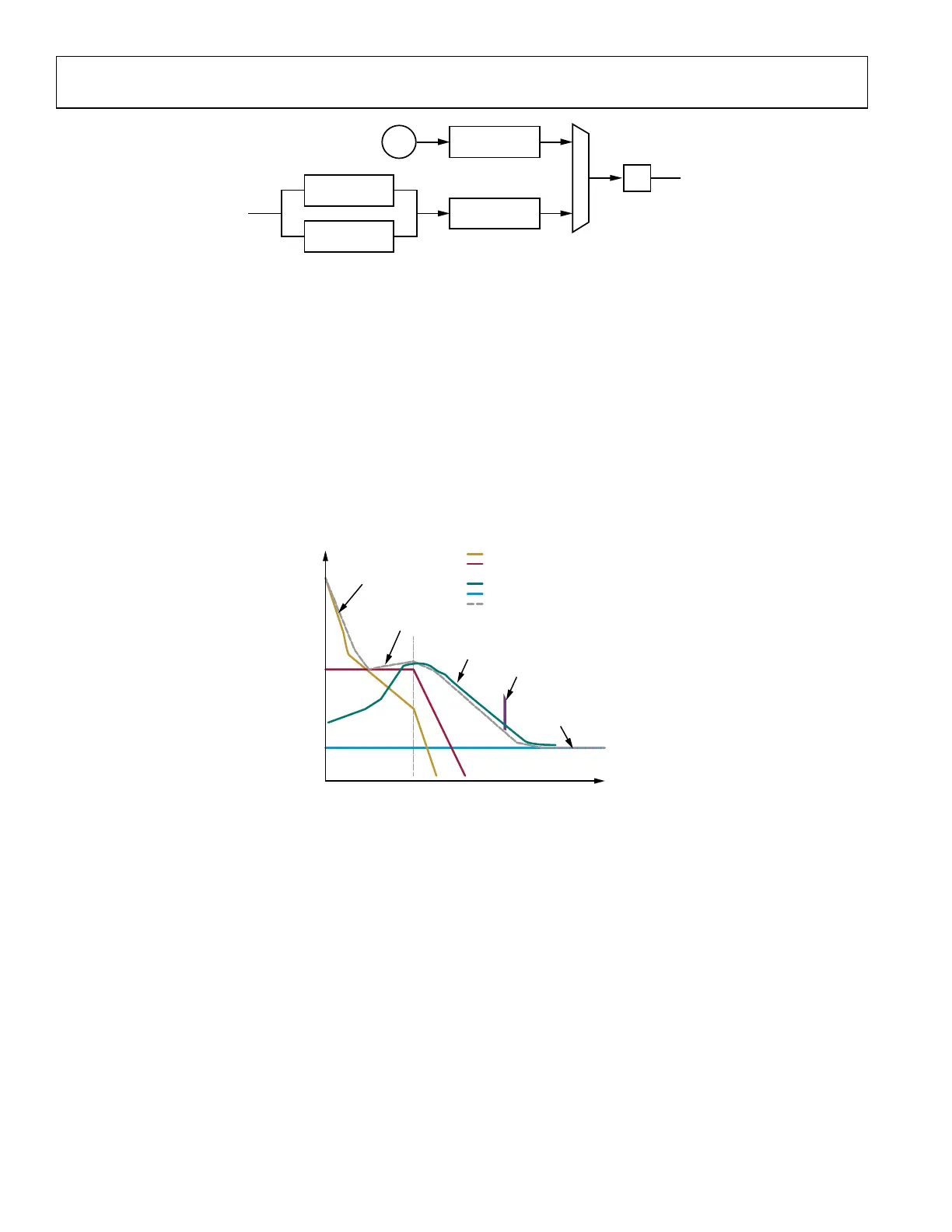
Figure 99. Rx Only with Long Propagation Delay
Tx Only with Long Propagation Delay
The ADRV9001 also supports Tx only case where the propagation delay is greater than the duration of a hop frame.
To achieve this, the user can specify a parameter as a part of the frequency hopping configuration, to delay the powering up of the Tx
delay the powering up of the Tx analog, in terms of hop frames. The user can then time the enabling of the interface, along with the using
the txRiseToAnalogOn timing parameters, to fine tune the delay.
The delay parameter specifies the delay in terms of hop frames after the first Tx setup rising edge has been received. By design, the
ADRV9001 enforces a minimum delay for both Tx and Rx of 1. However, for Tx only, this delay can be greater than 1. If the user sets it
to 0, the ADRV9001 defaults the delay to 1.
After the first Tx setup rising edge, the user must then continuously send a pulse train of Tx setup signals until the hop edge in which the
Tx frame begins on air. After this, the user can maintain any number of consecutive Tx frames, as long as the Tx setup is continuously
toggled. After the pulse train of Tx setup stops (meaning a hop edge without a preceding Tx setup rising edge), the Tx channel is
powered down at the next hop edge. A subsequent Tx setup begins the process again.
This example shows a four-frame delay, with the Tx frame starting on air at the fifth frame after the first Tx setup rising edge.
To account for the transition period between consecutive frames, the user may want to pad their valid data with guard symbols. In the
example, this is marked by the grey boxes. If the user desires, they can pad their data to keep the transition and dwell times consistent.
This is because the transition required for the first Tx frame is greater than that required for consecutive frames.
24159-496
FRAME 0
FRAMING ON AIR
NOT ON AIR
ON AIR
MAY OR MAY NOT BE ON AIR
FRAMING AT BBIC
PIN: HOP
PIN: Rx SETUP
Rx INTERFACE
Rx ANALOG POWER
t
RxPD
t
TxPD
FRAME 1 FRAME 2
DWELL
DWELLDWELL
DWELL
DWELL
DWELL
TRANSITION
FRAME 0
FRAME 1 FRAME 2
t
RxEnaRise2AnaOn
t
RxEnaSetup
TRANSITION
TRANSITIONTRANSITION TRANSITION
Figure 100. Tx Only with Long Propagation Delay
Tx Only with Short Propagation Delay
There is a restriction to how long before the hop edge the Tx setup falling edge must come. For profiles with very short propagation
delays, this means the interface will be on longer than required for valid data to reach the analog front end.
 Loading...