4-79
(6) Standby Output Power measurement: Standby Output Power
screen
Step Key operation Description
1. [Main Func on off] F6 Sets the Main Func on to display the Main Menu at the bottom of the screen.
2. [TX&RX Tester] F1 Sets TX&RX Tester mode.
The Setup Common Parameter screen appears.
3. [TX Measure] F1 Displays the first page of the TX Measure menu.
4. Next Menu [ ] Displays the second page of the Main Func menu.
5. [Start] F5 Sets Call Processing state to Idle.
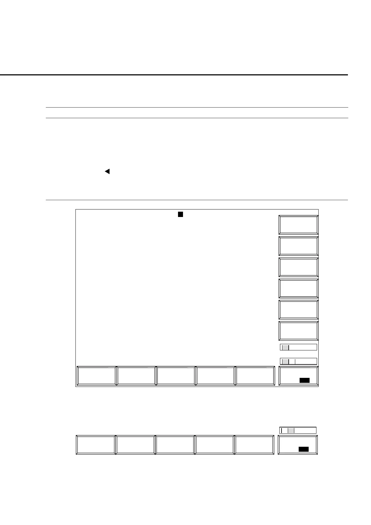
6. [Standby Output Power] F9 Displays the Standby Power Meter screen.
1
MT8801 99/12/31 12:00:00
<< Standby Output Power (CDMA) >>
Standby Pwr.
->
*
Back
Screen
Start
Standby
Output Pwr.
POWER : ******* dBm
**** mW
Calibration
M
U
1
2
Channel : 0000CH Frequency : 1000.000 000MHz Level : -10dBm
BS Output
Level
Main Func
On Off
#
###
#
1
Sync
Channel
Level
Paging
Channel
Level
Traffic
Channel
Level
Pilot
Channel
Level
Fig. 4-10 Standby Output Power Screen
The 2nd page of the main function keys on the Standby Output Power screen
1
Reference
Level
Main Func
On Off
#
2
4.3 CDMA Transmitter and Receiver Test --- TX and RX Tester Mode
 Loading...


