Section 4 Operation
4-2
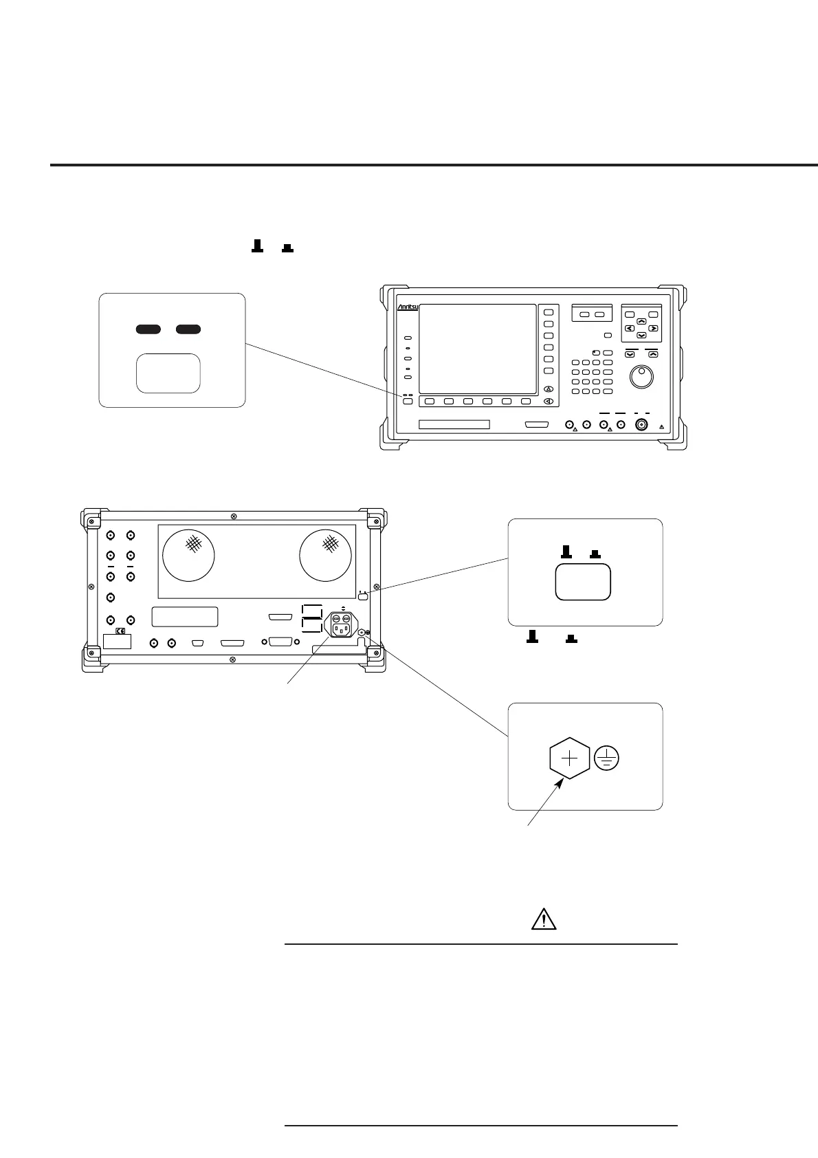
4.1 Turning on and off the Power
The MT8801C has two power switches: The Stby/On switch on the front panel and
O I
(main power) switch on the rear panel.
ParallelSerial
GPIB
10MHz
Buffered
Output
10MHz/13MHz
Reference
Input
~Line Input 350VA Max
47.5–63Hz
100–120V T 6.3A
200–240V T 6.3A
O I
WARNING
CAUTION
Detector
Output
Data Clock
Ext Trig
Input
Ext Trig
Output
Ext FM
Input
Demod
Output
BER Input
CDMA
Reference
Input
CDMA
Reference
Output
25 contacts 24 contacts
CDMA Timing
25 contacts
NAME PLATE
Stby
On
O I
O / I
switch
Frame grounding terminal:
Connect this
terminal to ground
to prevent electric
shock.
Stby / On
MT8801C Rear Panel
MT8801C Front Panel
AC power inlet
MT8801C
Radio Communication
Analyzer
300kHz-3GHz
Input/Output
Main
Output
300kHz-3GHz
50Ω
10W Max
20dBm Max
AUX
50Ω
InputAF OutputAF InputDUT Interface
Stby
Copy
Panel Lock
Local
Remote
On
Preset
Set
Cancel
Single
Continuous
Step
Measure
Cursor
F 7
F 8
F 9
F 10
F 11
F 12
F 1 F 6F 5F 4F 3F 2
Next Menu
Hz
µV
µs
kHz
mV
ms
MHz
dBµ/V
sec
GHz
dBm
dB
0
. - / +
Enter
123
56
BS
4
89
Shift
7
D
CA
µW
W
nW
mW
EF
B
30V Max
FDD
25 contacts
WARNING
• Protective grounding
If the power is turned on without protective grounding, op-
erator runs the risk of electric shock. If the MT8801C does
not have a three-pole (grounding type two-pole) power
outlet, be sure to connect the frame grounding (FG) termi-
nal on the rear panel or ground terminal of the accessory
power cable to ground before turning on the MT8801C
power.