5-9
5.3 Enabling the Service Request (SRQ)
All types of summary messages in the STB register can be enabled or disabled for
service requests (SRE) by using the program-controlling service request (SRQ) en-
able operation. The service request enable (SRE) register controls the generation of
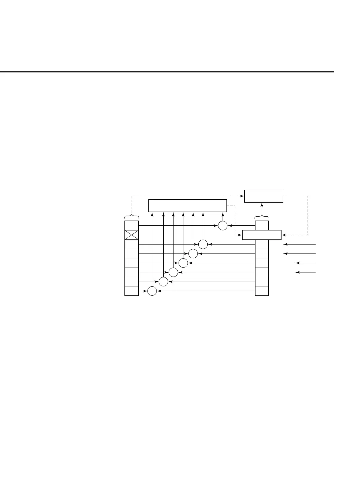
SRQ in bits 0 to 7 as shown in the diagram below.
Bits in the service request enable register correspond to bits in the status byte register.
If a bit in the status byte corresponding to an enabled bit in the service request enable
register is set to 1, the device makes a service request to the controller with the RQS
bit set to 1. For example, if bit 4 in the service request enable register is enabled, the
device makes a request for service to the controller each time the MAV bit is set to 1
when there is data in the output queue.
7
5
4
3
2
1
0
7
6
5
4
3
2
1
0
&
&
&
&
&
&
&
Logical OR
Service Request
Generation
MSS 6 RQS
Service request enable (SRE) re
ister
Status summary message
Status byte (STB) re
ister
Not used
ESB
MAV
ESB
(
ERR
)
ESB
(
END
)
Not used
Not used
disabled = 0, enabled = 128(2
7
)
Not used
disabled = 0, enabled = 32 (2
5
)
disabled = 0, enabled = 16 (2
4
)
disabled = 0, enabled = 8 (2
3
)
disabled = 0, enabled = 4 (2
2
)
disabled = 0, enabled = 2 (2
1
)
disabled = 0, enabled = 2 (2
0
)
(1) Reading the SRE register
The contents of the SRE register are read using the *SRE? common query. The
response message to this query is an integer from 0 to 255, which is the sum of
the bit digit weighted values in the SRE register. SRE register bits 0 to 5 and 7
are respectively weighted to 1, 2, 4, 8, 16, 32, and 128. The unused bit 6 must
always be set to 0.
(2) Updating the SRE register
The *SRE common instruction is used to write data to the SRE register. An
integer from 0 to 255 is added after the *SRE . fm3common instruction.
This integer indicates the total number of bits in the SRE register (weighted
values:1, 2, 4, 8, 16, 32, and 128), and sets the corresponding SRE register bit to
0 or 1.
A bit value of 1 indicates an enabled state; 0 indicates a disabled state. Always
ignore the value of bit 6.
5.3 Enabling the Service Request (SRQ)