Section 2 Device Messages
2-6
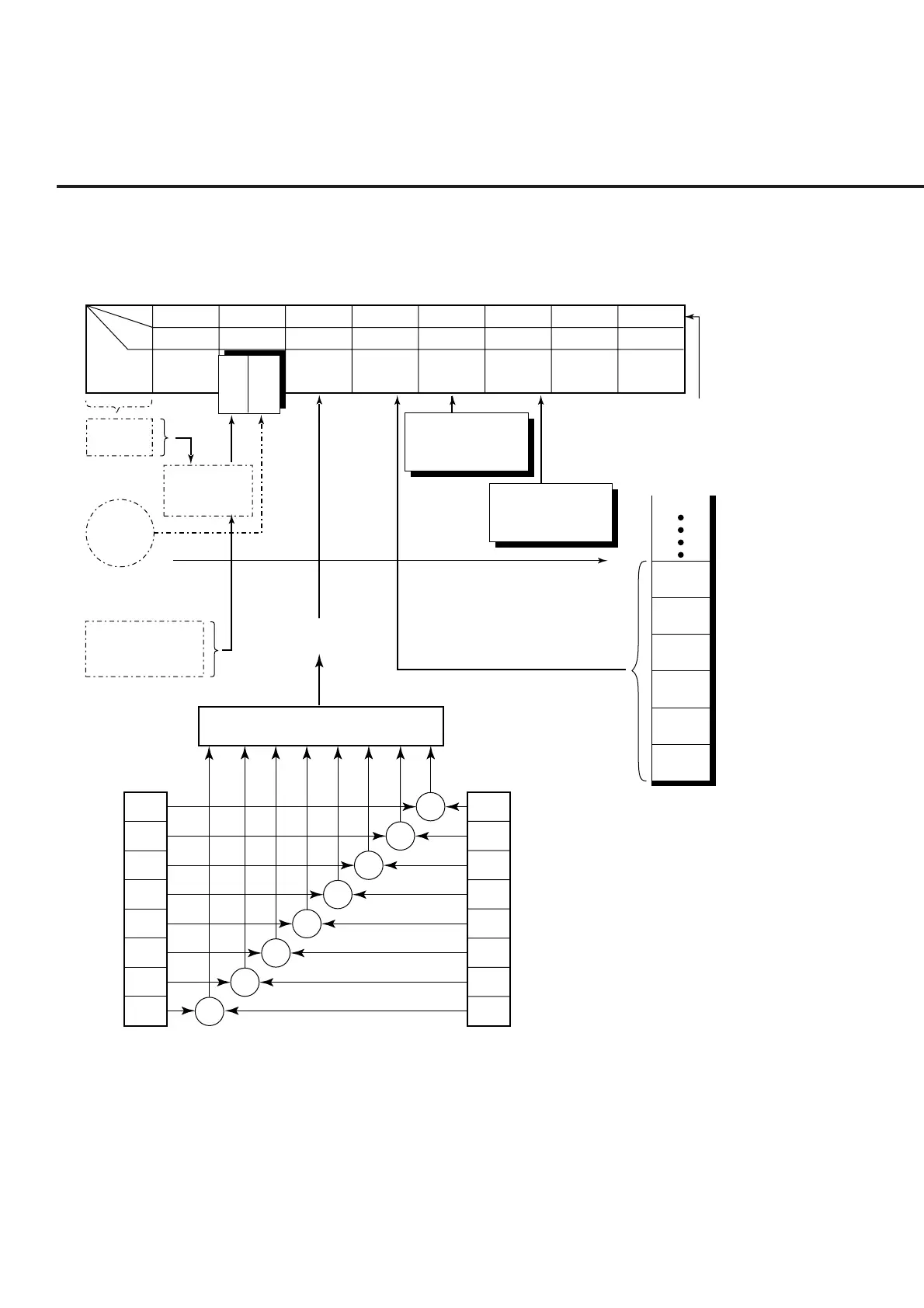
2.4 Status Messages
The diagram below shows the structure of service-request summary messages for the
status byte register (STB) used with the MT8801C.
7
6
5
4
3
2
1
0
&
&
&
&
&
&
&
Logical OR
Standard event status
register (ESR)
&
Standard event status
enable register (ESE)
7
6
5
4
3
2
1
0
Data
Data
Data
Data
Data
Data
Output queue
Event Summary Bit
(ESB)
Bit 7 Bit 6 Bit 5 Bit 4 Bit 3 Bit 2 Bit 1 Bit 0
END summary bit of
the extended (END)
register of the next page
DIO8 DIO7 DIO6 DIO5 DIO4 DIO3 DIO2 DIO1
ESB MAV ERR
Not used
END
Not used Not used
bit
Line
Summary bit
bit 0~5,7
Service Request
Generation
& of each
corresponding
bit
Service Request
Enable Request
bits 0 to 5, 7
MAV bit indicating that the output
queue is not empty
Message Available (MAV)
Status byte
(status message)
Power on (PON)
User request (URQ, not used)
Command error (CME)
Execution error (EXE)
Device-dependent error (DDE)
Query error (QYE)
Request for control of bus (RQC, not used)
End of operation (OPC)
ERR summary bit of
the extended (ERR)
register of the next page
M
S
S
R
Q
S
Standard Event Status (STB) Register
Note:
& indicates a logical product (AND).