Section 1 General
1-6
1.5 Specifications
The specifications of the MT8801C CDMA Measurement are listed in Table 1-6 be-
low.
The specifications of the MT8801C Option 12 are listed in Table 1-7 below.
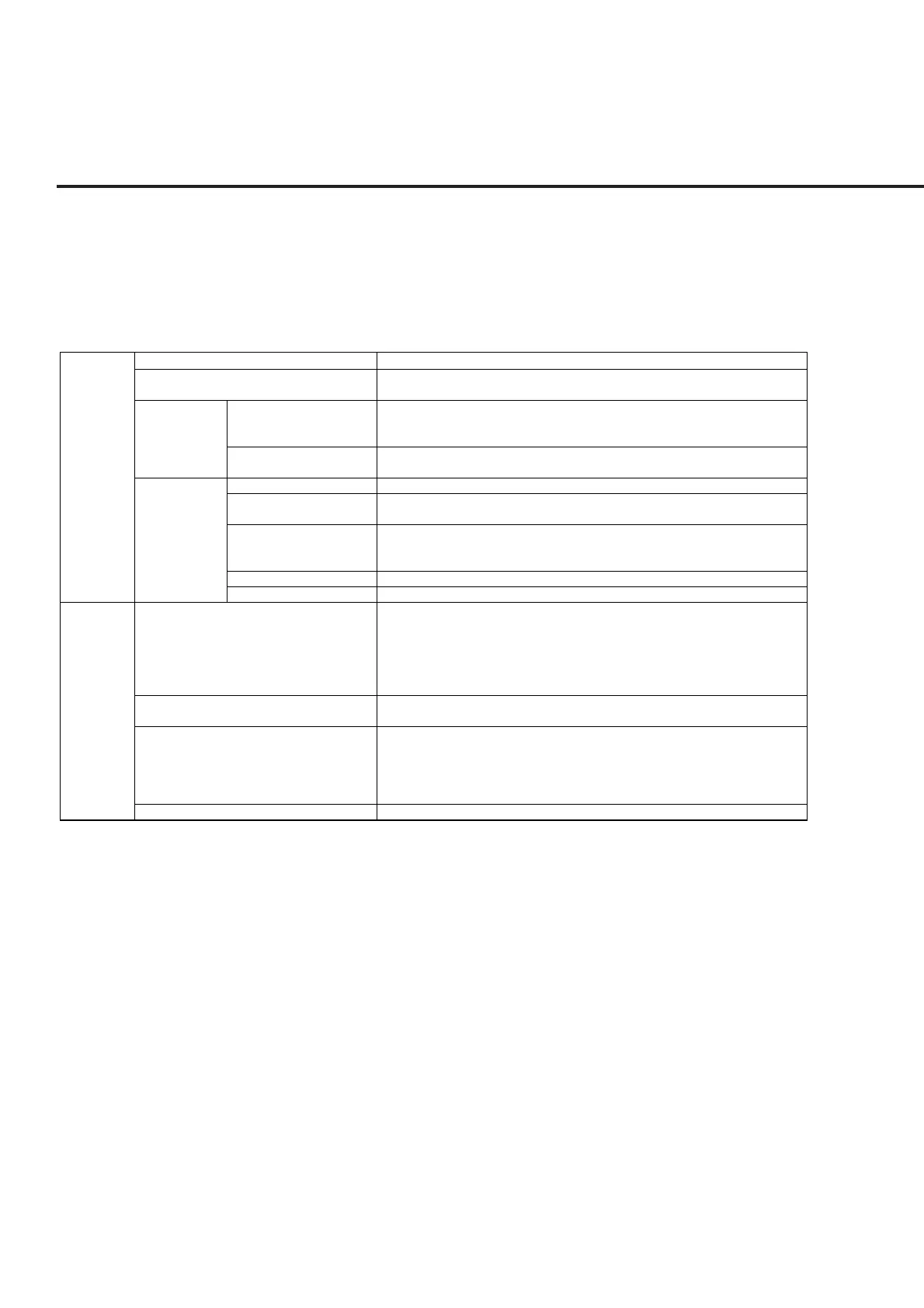
Table 1-6 MT8801C Specifications
Frequency range
Maximum input level
Input/output
connector
Reference
oscillator
Frequency range
Level range
Accuracy
Input connector
General
Power
meter
MAIN I/O connector
Auxiliary input connector,
Auxiliary output connector
Frequency
Starting characteristic
Aging rate
Temperature characteristic
External standard input
300 kHz to 3 GHz
+40 dBm (10 W) (MAIN connector)
+20 dBm (100 mW) (auxiliary input connector)
N-type connector
Impedance 50 Ω, VSWR ≤ 1.2 (Frequency ≤ 2.2 GHz)
VSWR ≤ 1.3 (Frequency > 2.2 GHz)
TNC connector
10 MHz
≤5 × 10
–8
/day
After 10 minutes of warm-up, refered to frequency after 24 hours of warm-up
≤2 × 10
–8
/day
≤1 × 10
–7
/year
Refered to frequency after 24 hours of warm-up
5 × 10
–8
(0 to 50°C) Refered to frequency at 25°C
10 MHz or 13 MHz (within ±1 ppm), Input level : 2 to 5 Vp-p
For CDMA measurement software : Only 1 channel of input code channel
824.01 to 848.97 MHz, 30 kHz step (IS-95A)
1850.00 to 1909.95 MHz, 50 kHz step (J-STD-008)
887.0125 to 888.9875 MHz, 898.0125 to 900.9875 MHz,
915.0125 to 924.9875 MHz, 12.5 kHz step (ARIB STD-T53)
For other measurement software : 300 kHz to 3 GHz
For CDMA measurement software : –10 to +40 dBm (MAIN connector)
For other measurement software : 0 to +40 dBm (MAIN connector)
For CDMA measurement software :
±10 % (18 to 28°C, –10 to +40 dBm, averaged, MAIN connector)
(After zero-point calibration and at signal-generator output level equal to or less than
–53 dBm)
For other measurement software : ±10 % (0 to 50°C, 0 to +40 dBm, MAIN connector)
MAIN connector only