Section 6 Peformance Tests
6-10
(4) Test procedures: Relative level accuracy of signal generator
Step Procedure
1. Initialize the MT8801C and the power meter.
2. Set the MT8801C as follows:
RF Input/Output: Main Set it on the Instrument Setup screen.
Using Specification: IS-95A Set it on the Setup Common Parameter screen.
CDMA Channel: 340 Ch Set it on the Setup Common Parameter screen.
BS Output Power Level: –33 dBm Set it on the Setup Common Parameter screen.
AWGN Level: Off Set it on the Setup Common Parameter screen.
3. Execute Start on the Setup Common Parameter screen of MT8801C. When “Call Proc. status:
Idle” is displayed, set the Loop mode using the GPIB command.
Command: TESTMODE INSPECLOOPBACK
4. Set the Pilot signal generation mode using the GPIB command.
Command: TESTPILOTCH ON
5. Execute BS Output Power Cal. using the GPIB command.
6. Press the Local key (release the external control) of MT8801C to display the Open Loop Time
Response screen.
7. Read the value (X) indicated on the power meter (about –33-dBm value indicated).
8. Set Step Value at 20 dB.
9. Press the BS Level Step Down Start key to reduce the output level by about 20 dB.
10. Read the value (Y) indicated on the power meter (about –53-dBm value indicated).
11. Change the settings as “Using Specification: J-STD-008” and “CDMA Channel: 600” and perform
the measurement as same as above to read the result.
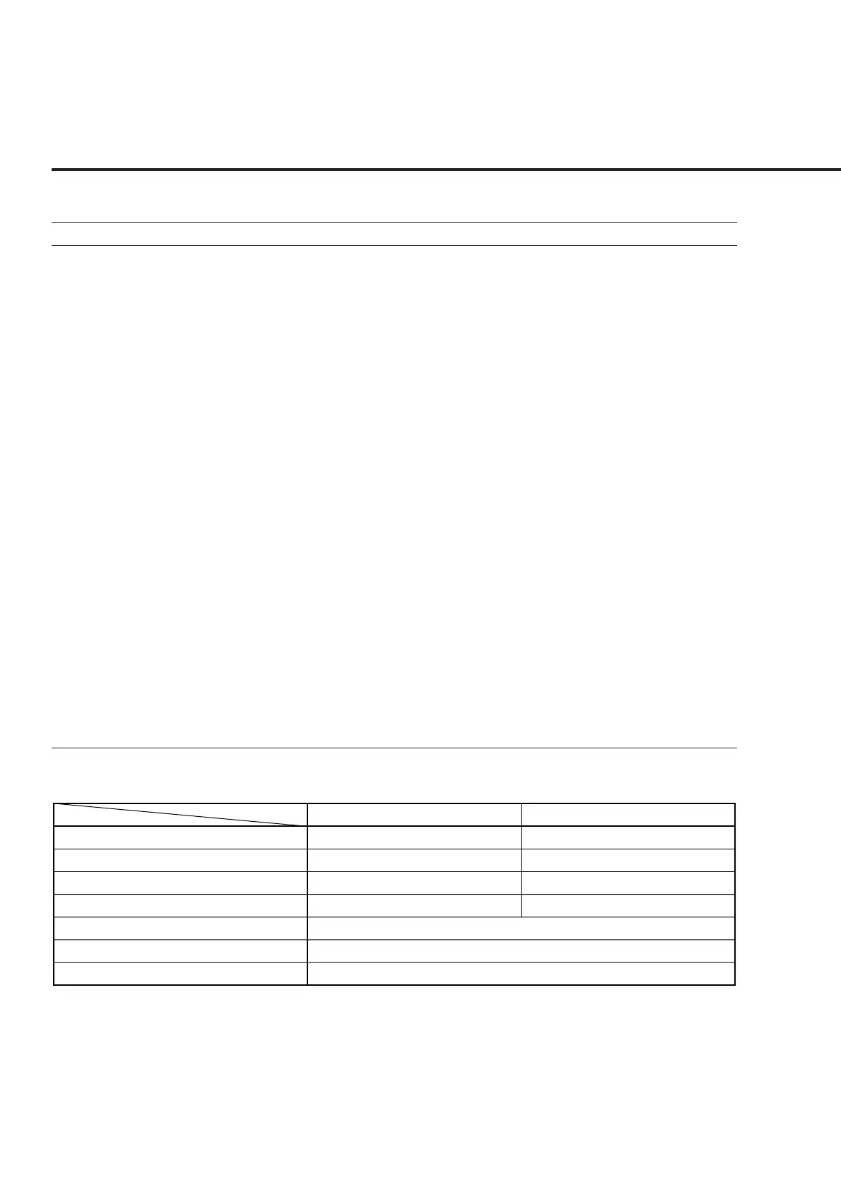
Relative level accuracy of signal generator
X
Y
Y−X
Relative Level Accuracy (Y−X+20)
Measurement uncertainty
Effective lower limit
Effective upper limit
600 CH (1960 MHz)
__________ dBm
__________ dBm
__________ dB
__________ dB
±0.03 dB
−0.17 dB
+0.17 dB
340 CH (880.2 MHz)
__________ dBm
__________ dBm
__________ dB
__________ dB