6.3 - Main Power Terminal Plug Connections
6.3.1 - Signal Ground
This lead allows users to use the PS8 in an OEM application for increased compatibility to factory
radios using a variety of balanced and common ground applications.
6.3.2 - Illumination
If using the ARC Audio PSC controller (Sold Separately), this lead allows users to interface with the
vehicles parking light circuit to trigger the onboard controller illumination circuit . This
function is user denable for the type of convenient trigger that is available in reference to the
location of the PS8's installation.
6.3.3 - Prole 2
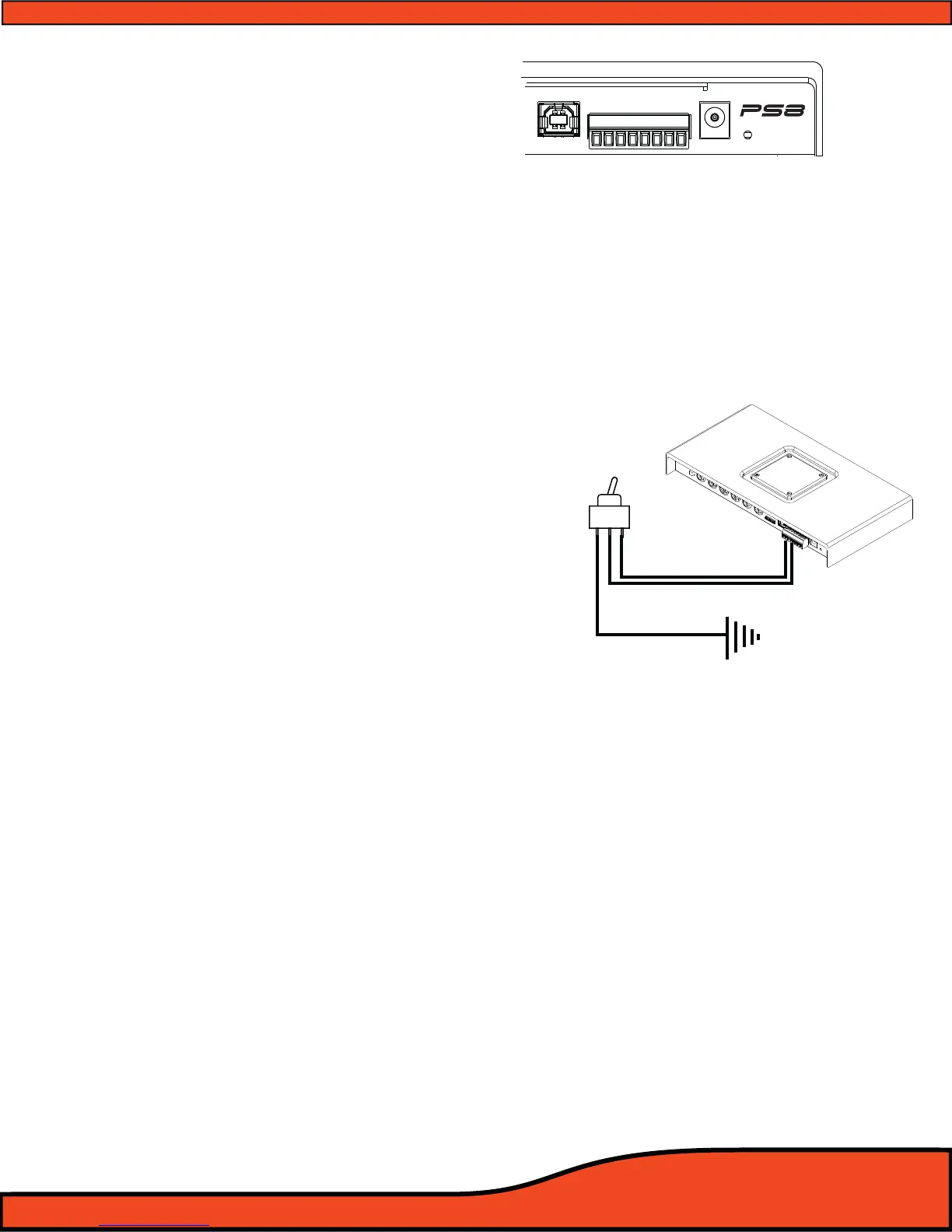
Using a 3 position latching toggle switch, connect
this lead to ground to switch the PS8 to its P3 user
dened preset without the need of a laptop or
controller
(See diagram 6.5)
6.3.4 -Prole 1
Using a 3 position latching toggle switch, connect
this lead to ground to switch the PS8 to its P2 user
dened preset without the need of a laptop or
controller
(See diagram 6.5)
6.3.5- Remote Output
This lead output is used to activate and control the remote turn on of additional devices including
ampliers, relays etc.
(See diagram 6.5)
TAKE SPECIAL NOTE- The PS8's remote output current capacity is rated at 250mA. This voltage out is capable
of driving several ARC Audio ampliers without the need of a relay. If you are using ampliers other than ARC
Audio, and they do not use an ultra low current microprocessor-triggered turn on circuit, we recommend
using a quality low current relay for this operation. Please be sure that the relay trigger requirement does not
exceed the 250mA rating.
WARNING- When using the PS8 in your vehicle’s system, you must trigger all of your system’s ampliers o of
the PS8's Remote Turn- on output circuit. The remote output lead timing is controlled and customizable thru
the setup function of the user utility, allowing the user to control the exact timing on and o requirements for
their particular application, reducing, if not eliminating, the possibility of turn on/o pops and other
unwanted related noises, preventing possible damage to your system’s components.
USB
+12V
GND
REM - IN
REM - OUT
P - 1
P - 2
ILLUM
SIG GND -
Diagram 6.5