11.5 - "Meters"
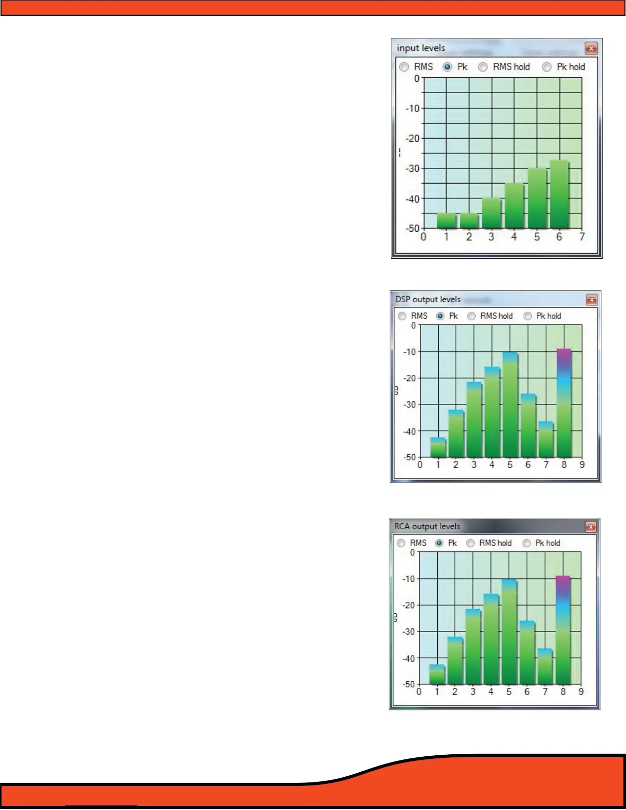
11.5.1 - Signal Input
Access to the Signal Input VU meter on the
PS8's user interface.
(See diagram 11.26)
The onboard Signal Input VU meter gives
users the ability to visually see the indi
vidual signal level of all 6 channels of input
of the PS8. Display features include phys-
ical signal level, peak signal level and RMS
signal level. This meter is also used in co-
junction with the input panel for signal
summing of some vehicles OEM factory
radio signals.
11.5.2 - DSP Output
Access to the DSP Output VU meter on the
PS8's user interface.
(See diagram 11.27).
The onboard DSP Signal Output VU meter
gives users the ability to visually see the
individual signal level of all 8 channels of
output post mixer/router controls on the
PS8. This Meter is a great tool to use to
verify signal level and correct conguration
of the router/mixer into the DSP's cros-
sover section to prevent overdriving or
misrouted signals into the tuning portion
of the DSP. Display features include physi-
cal signal level, peak signal level and RMS
signal level.
11.5.3 - Signal Output
Access to the Signal Output VU meter on
the PS8's user interface.
(See diagram 11.28).
The onboard Signal Output VU meter gives
users the ability to visually see the indi-
vidual signal level of all 8 channels of signal
as it exits the PS8. Display features include
physical signal level, peak signal level and
RMS signal level.
Diagram 11.26
Diagram 11.27
Diagram 11.28