iPAM400 – Product Manual
U-0629-0171.doc – Issue: 04 complete, approved
Page 37 of 138
13. Connect power to the mainframe.
a. Connect the AC mains power supply to the mainframe.
b. Connect the DC power supply to the mainframe, if used.
c. Power the mainframe on by turning the mains isolation switch on, and then turning the battery
isolation switch on.
d. Wait a moment for the iPAM400 application to start. During the start-up, the processor LED on
the front panel flashes fast. The processor LED will flash slowly to indicate that the iPAM400
has started and is operational.
!
!
This product contains wiring that is energised to 230 V RMS AC mains and 100 V RMS
audio signals at up to 20 kHz.
Terminals marked with the
symbol are hazardous, and the external wiring connected
to these terminals requires installation by qualified personnel only.
14. Commission the mainframe. Refer to Section “6 Commissioning” (page 59).
!
!
Do not fit the mainframe front panel until connections to the mainframe and
peripherals have been made and the system tested.
Once the front panel is fitted, the power ON/OFF switch and the Reset/Shut Down
button will not be accessible.
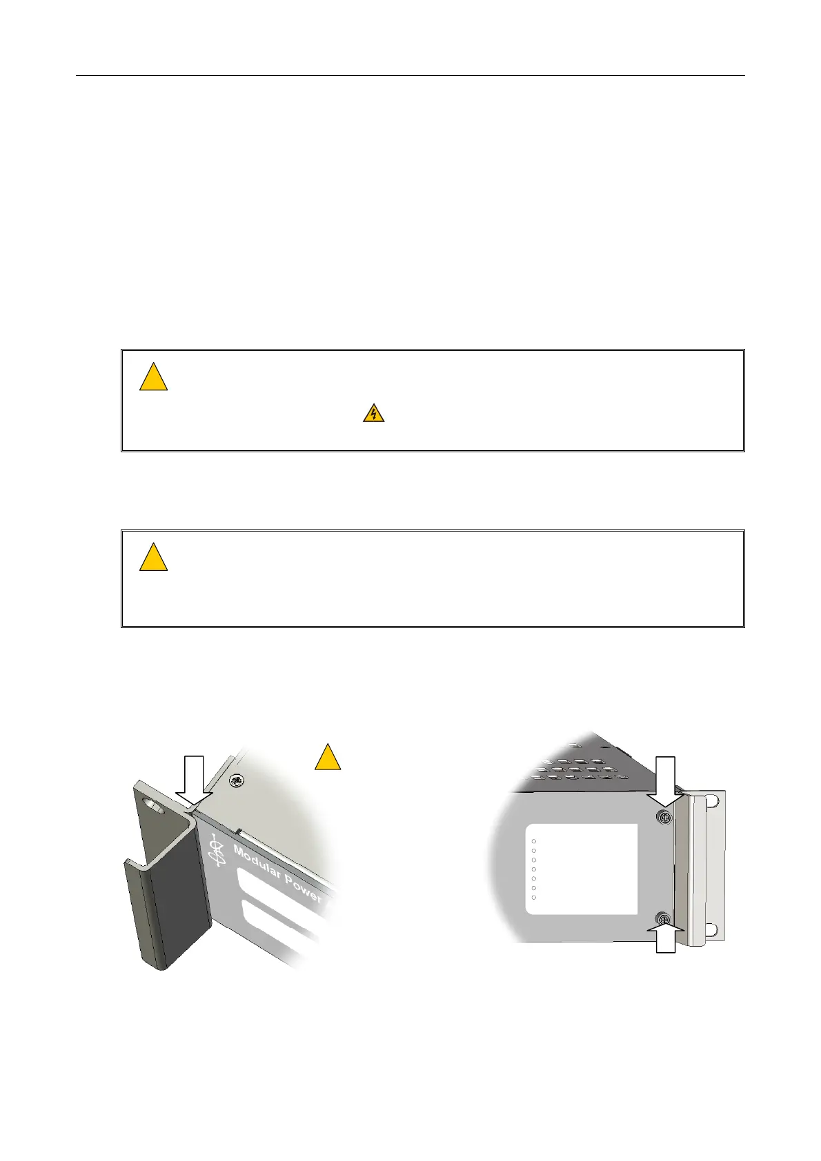
15. Fit the amplifier mainframe panel by sliding its left end under the left iPAM400 handle, and fixing its
right end using the two captive M3 Pozidriv screws; see Figure 14.
Figure 14 Fixing the mainframe front panel
LEFT END UNDER HANDLE
iPAM400
fault
sync
processor
ethernet
aux
battery
mains
CAPTIVE M3 SCREW
(POZIDRIV)
CAPTIVE M3 SCREW
(POZIDRIV)
THE FRONT PANEL SHOULD
MATCH THE CONFIGURATION OF
AMPLIFIER MODULES.
!
!