Manual, Air Module, AH2
Document #9620-20-D-AH2-09
Pinnacle Park • 1031 Goodworth Drive • Apex, NC 27539 • Tel: 919.772.0115 • Fax: 919.772.8259 • www.ati-ia.com • Email: info@ati-ia.com
D-4
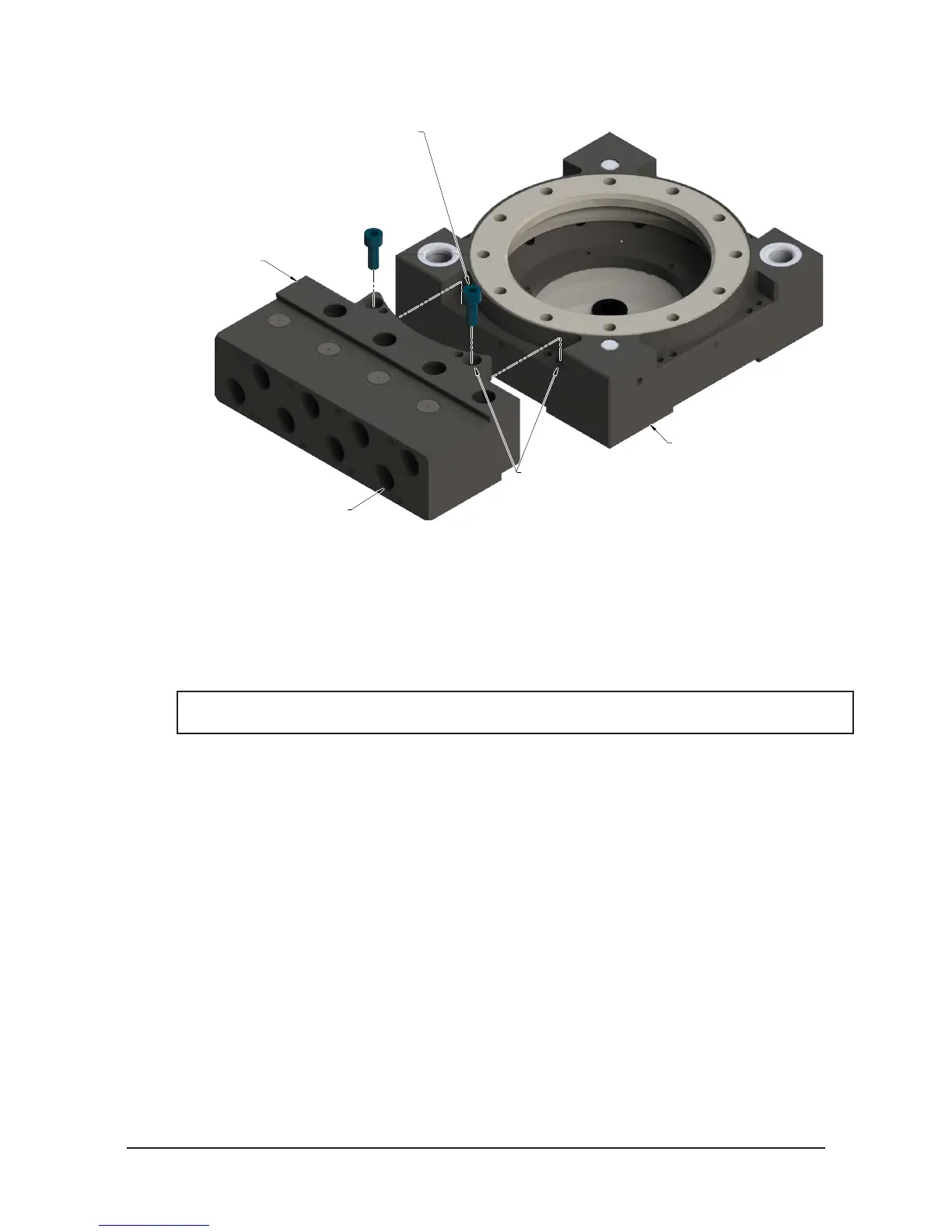
Figure 2.1—Installation and Removal of the Module
9121-AH2-T (Shown)
Tool Changer
(2) M6 Socket Head Screw
Use Ledge Mounting Feature
to Properly Align Module
(8) Customer Air Connection
2.2 Module Removal
Tools required: 5 mm Allen wrench
Supplies required: Clean rag
1. Place the Tool in a secure location.
2. Uncouple the Master and Tool plates.
3. Turn off and de-energize all energized circuits (e.g. electrical, air, water, etc.).
NOTICE: Debris can be expelled at high velocity during the purge, take all required safety
precautions.
4. All customer plumbing connections to the module must be purged.
a. Verify that the supply lines are turned off.
b. Cover the valves with a rag for safety.
c. Manually actuate the self-sealing valves to purge the line pressure.
5. Use a marker pen to indicate where the module is to be re-installed.
6. Disconnect air plumbing to the module.
7. Remove the (2) M6 socket head cap screws using a 5 mm Allen wrench
8. Remove the module from the Tool Changer or Utility Coupler.