Manual, Robotic Tool Changer, QC-210
Document #9620-20-B-210 Series Base Tool Changer-26
Pinnacle Park • 1031 Goodworth Drive • Apex, NC 27539 • Tel: 919.772.0115 • Fax: 919.772.8259 • www.ati-ia.com • Email: info@ati-ia.com
B-8
2.2 Master Plate Installation
Tools required: 8 mm Allen
®
wrench (hex key), torque wrench
Supplies required: Clean rag, Loctite
®
242
1. Clean the mounting surfaces.
2. If required, install the interface plate to the robot arm, align using the boss or dowel pins and secure with
customer supplied fasteners.
3. Align the dowel pins to the corresponding holes in the Master plate and secure the Master plate to the
robot arm or interface plate with customer supplied (10) M10-1.5 socket head cap screws using an 8 mm
Allen wrench. Refer to Section 8—Drawings for mounting pattern. Apply Loctite 242 to threads (see
Table 2.1 for proper fasteners and torque).
NOTICE: If an ATI interface plate is used, fasteners to mount the Master plate is supplied with
the interface plate.
4. Connect utilities to the appropriate module and Master plate connections. For pneumatic lock and unlock
connection refer to Section 2.7—Pneumatic Requirements.
5. After the procedure is complete, resume normal operation.
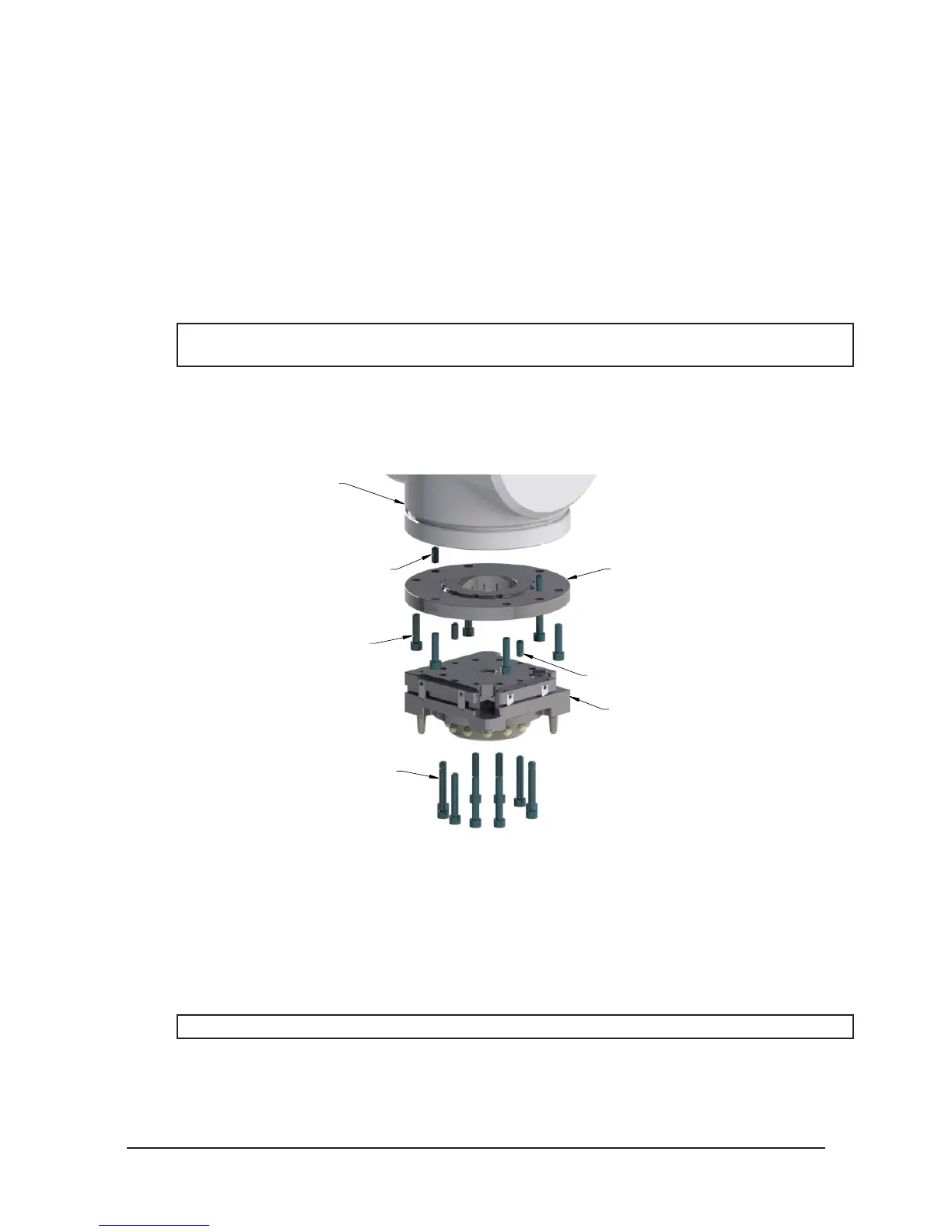
Figure 2.1—Typical Master Plate Installation
Robot Arm
Robot Interface Plate
(Customer Supplied)
(If required, custom RIP’s
(10) M10-1.5 Socket Head Cap Screw
(Refer to Table 2.1)
(Customer Supplied)
Master Plate
Dowel Pin (Customer Supplied)
Socket Head Cap Screw
(Customer Supplied)
Dowel Pin (Customer Supplied)
are available from ATI.)
2.3 Master Plate Removal
Tools required: 8 mm Allen wrench (hex key)
1. Place the Tool in a secure location.
2. Uncouple the Master and Tool plates.
3. Turn off and de-energize all energized circuits (e.g. electrical, air, water, etc.).
4. Disconnect all utilities (e.g. electrical, air, water, etc.).
NOTICE: Support the Master plate while removing the fasteners.
5. Remove the (10) M10 socket head cap screws connecting the Master plate to the robot arm or interface
plate using an 8 mm Allen wrench.