Quick Change Installation and Operation Manual
Document #9620-20-E-ED15-04
Pinnacle Park • 1031 Goodworth Drive • Apex, NC 27539 USA • Tel: 919.772.0115 • Fax: 919.772.8259 • www.ati-ia.com • Email: info@ati-ia.com
E-7
5. Troubleshooting and Service Procedures
The following section provides troubleshooting and service information to help diagnose conditions and repair the
Tool Changer or control/signal module.
DANGER: This module has a voltage of 50 V or greater, NO contact should be attempted
before removing power. This especially includes separation or insertion of the mating
connectors or any contact with the Tool Changer or its components. Arcing and damage will
occur if this is not observed. Remove power before attaching, disconnecting any cables or
attempting any maintenance of Tool Changer.
WARNING: Do not perform maintenance or repair on Tool Changer or modules unless the
Tool is safely supported or docked in the tool stand and all energized circuits (e.g., electrical,
air, water, etc.) have been turned off. Injury or equipment damage can occur with Tool not
docked and energized circuits on. Dock the Tool safely in the tool stand and turn off all
energized circuits before performing maintenance or repair on Tool Changer or modules.
5.1 Troubleshooting
The troubleshooting table is provided to assist in diagnosing issues that may cause the Tool Changer not to
function properly.
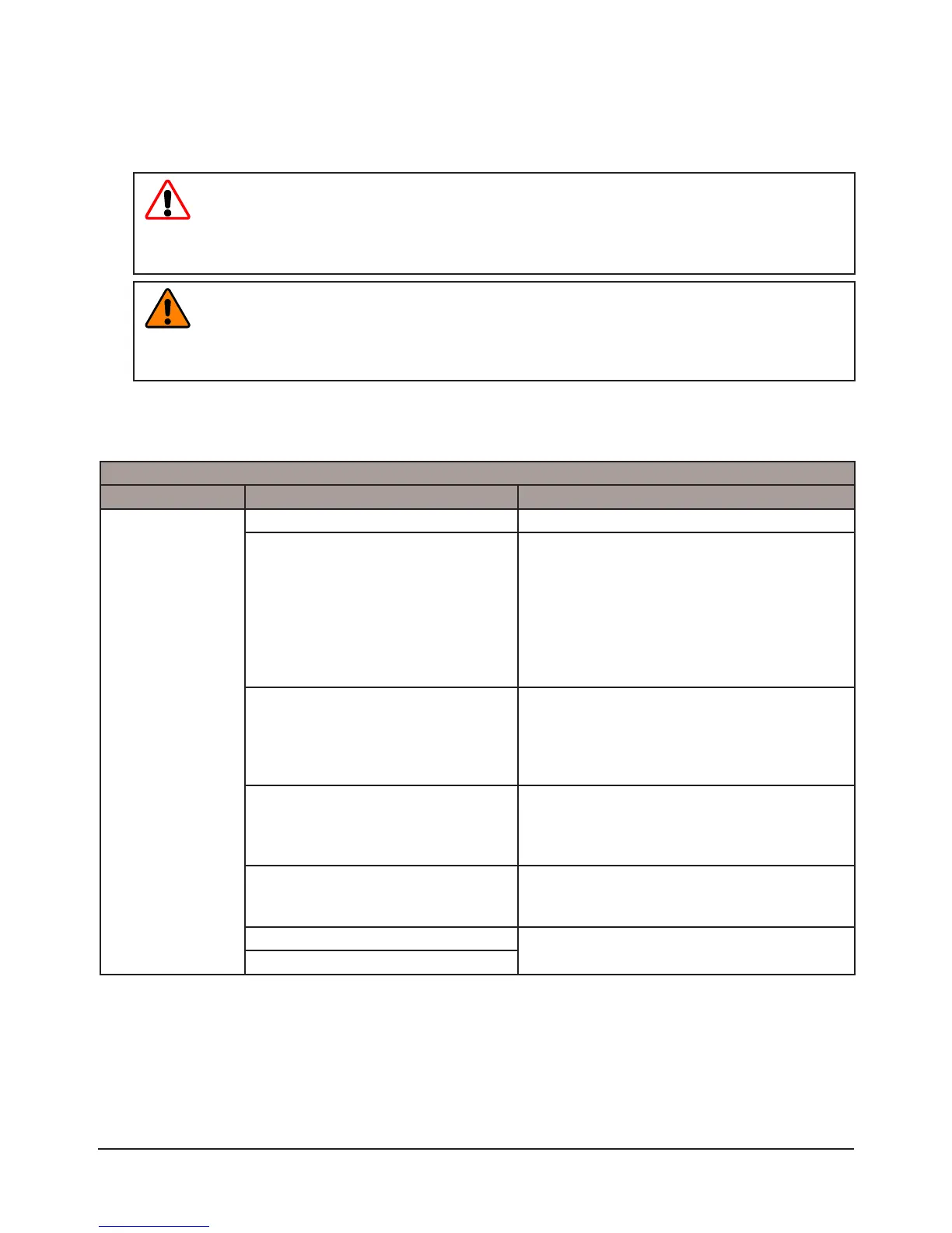
Table 5.1—Troubleshooting
Symptom Possible Cause Correction
Signal(s)
intermittently
functioning or not
functioning at all
Object trapped between modules Remove object, then re-attempt coupling.
Servo module contact pin
contamination
Ensure that the spring pins on the Master-
side can move freely and are not bound by
debris. Clean the spring pins to restore free
operation. Clean Tool-side module contacts,
refer to
Section 4.1—Pin Block Inspection
and Cleaning. Inspect seal, replace if
damaged refer to Section 5.2.1—V-ring Seal
Replacement
Contact pin separation due to air
supply to Tool Changer
Ensure that the Tool Changer has proper
pneumatic connections and air is supplied
to proper specication. Refer to Tool
Changer section of this manual for air supply
requirements.
Coupling/uncoupling Tool Changer
under load
Revise operating procedures to only couple/
uncouple with power disconnected and
discharged. Field replacement of module
contacts is not possible.
Cable damage: Pinched, torn, or
fatigued cables
Examine cables for damage, perform a
continuity test on cables and replace any bad
cables.
Servo module damaged
Refer to
Section 5.1.1—Servo Module, Drive,
or Motor Troubleshooting Procedure.
Drive or motor damaged

 Loading...