Manual, Robotic Tool Changer, QC-210
Document #9620-20-B-210 Series Base Tool Changer-26
Pinnacle Park • 1031 Goodworth Drive • Apex, NC 27539 • Tel: 919.772.0115 • Fax: 919.772.8259 • www.ati-ia.com • Email: info@ati-ia.com
B-24
Table 5.1—Troubleshooting
Symptom Cause Resolution
Units Equipped with Electrical/Servo/Control/Signal Modules
Loss of
Communication
Debris in thed around contact pins.
Contact Pin worn or damaged.
Inspect V-ring seal for damage, replace damaged seal. Refer to
Section 5.2.2—V-ring Seal Replacement
Cable connections loose or cables
damaged
Check that cable connection are secure and cables are not
damaged.
5.2 Service Procedures
The following service procedures provide instructions for component replacement.
5.2.1 Sensor Replacement Procedures
NOTICE: The Lock and Unlock sensor assemblies are precision aligned and
permanently assembled at the factory. Do not attempt to disassemble and rebuild.
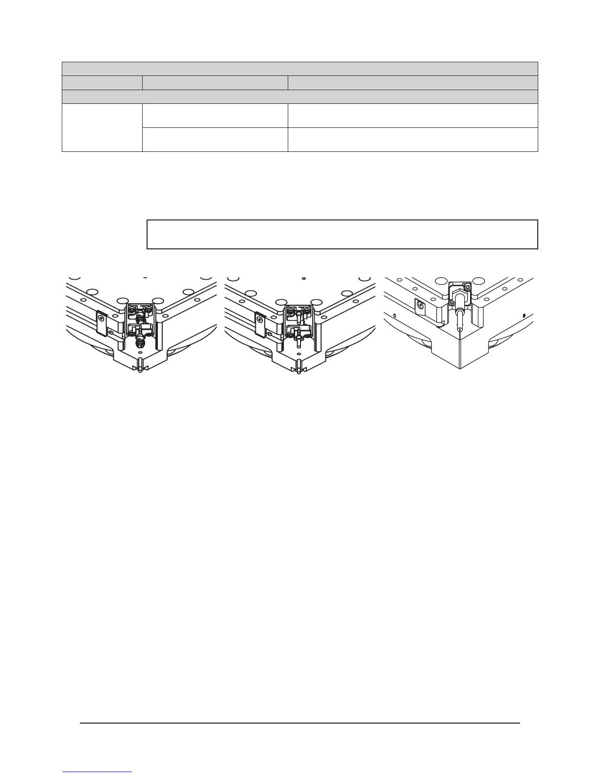
Figure 5.1—Determine what type of Lock/Unlock sensors the Tool Changer uses:
Lock and Unlock Sensor
Assembly Replacement (ST and
SU Sensor Designation)
Refer to Section 5.2.1.1—Lock
and Unlock Sensor Replacement
(ST and SU Sensor Designation)
Lock and Unlock Sensor
Assembly Replacement (Serial
Numbers QM0821 and higher)
Refer to Section 5.2.1.3—Lock
and Unlock Sensor Assembly
Replacement (Serial Numbers
QM0821 and higher)
Lock and Unlock Sensor
Assembly Replacement
Refer to Section 5.2.1.4—Lock
and Unlock Sensor Assembly
Replacement (with Sensor
Assemblies)
5.2.1.1 Lock and Unlock Sensor Replacement (ST and SU Sensor
Designation)
Parts required: Refer to Section 6—Serviceable Parts
Tools required: 2.5 mm Allen wrench (hex key), torque wrench
Supplies required: Loctite 222
1. Place the Tool in a secure location.
2. Uncouple the Master and Tool plates.
3. Turn off and de-energize all energized circuits (e.g. electrical, air, water, etc.).
4. Disconnect the sensor cable connector from the lock and/or unlock sensor.
5. Using a 2.5 mm Allen wrench, remove the (2) M3 socket head cap screws that
secure the lock and/or unlock sensor assembly to the Tool Changer body. Pull the
sensor assembly straight out from the Tool Changer body.
6. Remove the lock and/or unlock sensor assembly from the cable channel of the Tool
Changer body. There is an O-ring around the cylinder barrel, ensure O-ring came
off with old sensor before continuing. Discard the removed sensor assembly.