Manual, Control and Signal Module, SA2 SA3
Document #9620-20-C-SA2 SA3-04
Pinnacle Park • 1031 Goodworth Drive • Apex, NC 27539 • Tel: 919.772.0115 • Fax: 919.772.8259 • www.ati-ia.com • Email: info@ati-ia.com
C-6
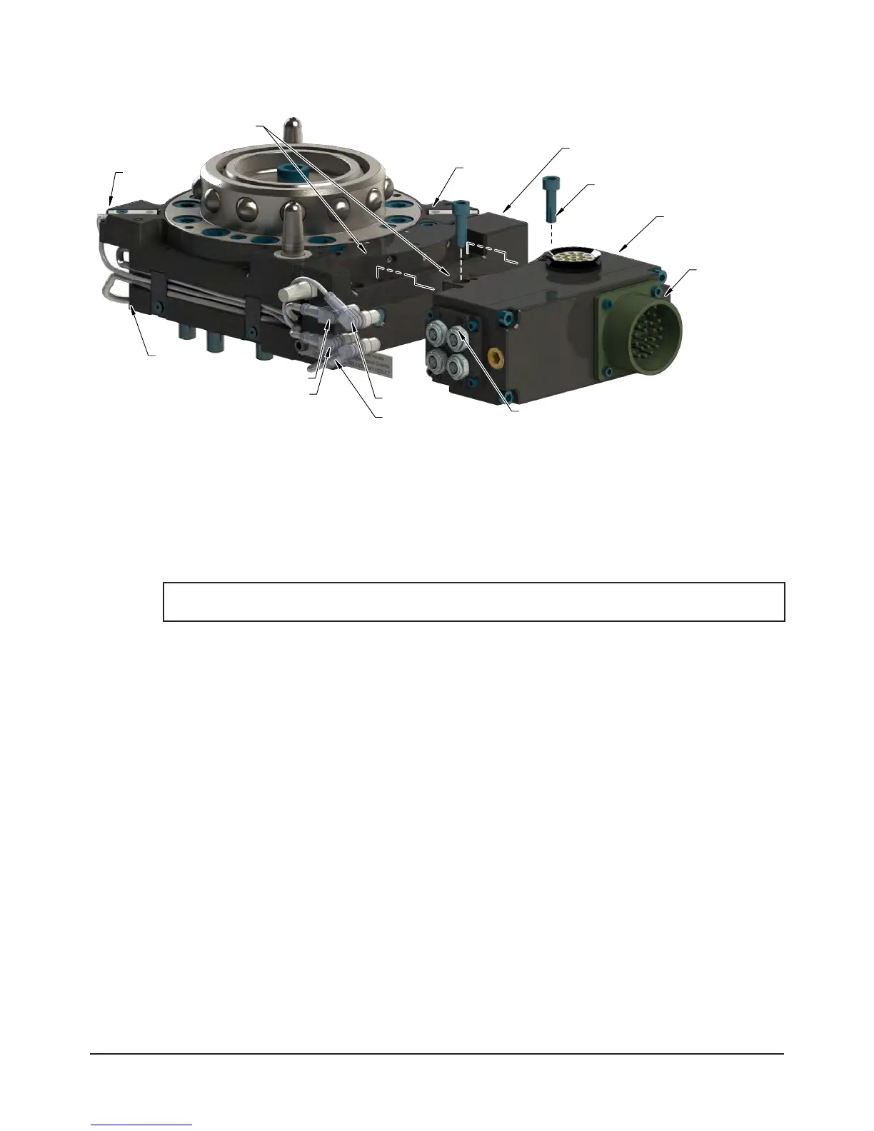
Figure 2.1—Master Module Installation and Removal
Amphenol
Connector
Master Module
RTL, Lock, and Unlock
Sensor Connectors
R2 Connector
U Connector
L Connector
R2 Sensor
R1 Sensor
(2) M6 Socket Head Cap Screws
Use Ledge Mounting Feature
to Properly Align Module
Air Adapter on Master Side (Shown)
Tool Changer
R1 Connector
2.2 Master Module Removal
Refer to Figure2.1 for Master module removal instructions.
Tools required: 5mmAllenwrench
1. If the Tool Changer is already installed, place the tool safely in the tool stand and uncouple the Tool
Changer to allow clear access to the Master and Tool plates of the Tool Changer.
2. Turn off and de-energize all energized circuits (e.g. electrical, air, water, etc.).
NOTICE: Mark the Lock, Unlock, and RTL sensor cables prior to disassembly so the cables can
be reinstalled to the appropriate sensor.
3. Disconnect the Lock (L), Unlock (U), and RTL (R1), and RTL (R2) sensor cable connectors from the
module.
4. Disconnect (e.g. power, signal, auxiliary, etc.) cables from the control/signal module.
5. Support the control/signal module, remove the (2) M6 socket head cap screws using a 5 mm Allen
wrench and lower the module until it clears the guide pin.