Manual, Robotic Tool Changer, QC-210
Document #9620-20-B-210 Series Base Tool Changer-26
Pinnacle Park • 1031 Goodworth Drive • Apex, NC 27539 • Tel: 919.772.0115 • Fax: 919.772.8259 • www.ati-ia.com • Email: info@ati-ia.com
B-35
5.2.3 Alignment Pin Replacement
Parts required: Refer to Section 6—Serviceable Parts
Tools required: 3 mm or 4 mm Allen wrench (hex key), torque wrench
Supplies required: Clean rag, Loctite 242, MobilGrease XHP222
1. Place the Tool in a secure location.
2. Uncouple the Master and Tool plates.
3. Turn off and de-energize all energized circuits (e.g. electrical, air, water, etc.).
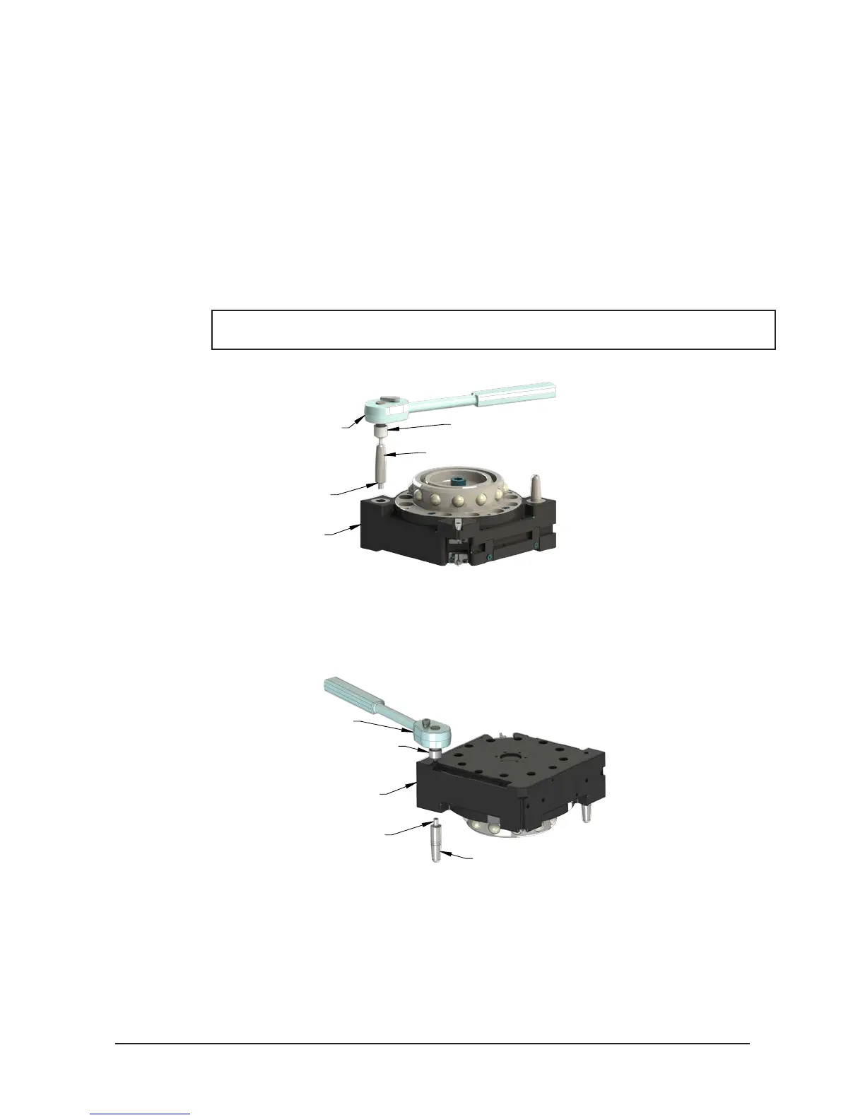
4. Unscrew the alignment pin assembly from the Master plate using a 4 mm Allen Wrench (see
Figure 5.13). If the alignment pin cannot be removed using the Allen Wrench in the tip, go to
step 5. If the alignment was remove the go to step 7.
NOTICE: If the for any reason the pin cannot be removed using the Allen Wrench in the
tip, it may be necessary to remove the it by other means, such as locking pliers.
Figure 5.13—4 mm Allen Wrench
Ratchet Wrench
4 mm Allen Wrench Socket
Alignment Pin Assembly
Set Screw
Master Plate
5. Another approach would be to use the access hole in the back side of the Master plate. If no,t
already removed, remove the Master plate refer to Section 2.3—Master Plate Removal. Use a
3 mm Allen wrench to remove the alignment pin from the back side of the Master plate. Refer
to Figure 5.14.
Figure 5.14—3 mm Allen Wrench
Ratchet Wrench
3 mm Allen Wrench Socket
Alignment Pin Assembly
Set Screw
Master Plate
6. Once the alignment pin has been removed, verify that the assembly (pin and set screw) are
intact. If the set screw portion of the assembly did not come out, it will be necessary to remove
the it separately using the access hole in the back plate of the Master plate.
7. Apply Loctite 242 and install the new alignment pin assembly into the bushing on the Tool
Changer. Tighten to 60 in-lbs (6.8 Nm) using a 4 mm Allen wrench.
8. Apply MobilGrease XHP222 Special grease to the alignment pin (see Section 4.2—Cleaning
and Lubrication of the Locking Mechanism and Alignment Pins).
9. After the procedure is complete, resume normal operation.