Manual, Air Adapters
Document #9620-20-C-Jxx Air Adapters-02
Pinnacle Park • 1031 Goodworth Drive • Apex, NC 27539 • Tel: 919.772.0115 • Fax: 919.772.8259 • www.ati-ia.com • Email: info@ati-ia.com
C-7
2.4 Air Adapter Removal for QC-310, QC-313, QC-510, QC-1210
NOTICE: Depending on maintenance or repair being performed, utilities to modules and Master
plate may need to be disconnected.
Tools required: 5 mm Allen wrench (hex key), 4 mm Allen wrench (hex key)
1. If the Tool Changer is already installed, dock the Tool side of the Tool Changer safely in the tool stand
and uncouple the Tool Changer to allow clear access to the Master and Tool plates of the Tool Changer.
2. Turn off and de-energize all energized circuits (e.g. electrical, air, water, etc.).
3. Remove the control/signal module off the air adapter. Refer to the control /signal module manual for
instructions.
4. Remove the (2) M5 socket head cap screws and the (2) M6 socket head cap screws and lift the air
adapter off the Tool Changer.
5. Make sure that the O-rings are retained at the Master side Flat ‘A’ mounting interface.
2.5 Tool Adapter Assembly Installation
Tools required: 5 mm Allen wrench (hex key), 4 mm Allen wrench (hex key), torque wrench
Supplies required: clean rag
1. If the Tool Changer is already installed, dock the Tool side of the Tool Changer safely in the tool stand
and uncouple the Tool Changer to allow clear access to the Master and Tool plates of the Tool Changer.
2. Turn off and de-energize all energized circuits (e.g. electrical, air, water, etc.).
3. It may be necessary to clean the mounting surface on the Tool Changer or Utility Coupler prior to
installing the air adapter in order to remove any debris that may be present.
4. Using the ledge feature as a guide, place the tool adapter assembly adjacent to the ‘A’ mounting surface.
Align the tool adapter assembly using the dowels in the bottom of the ledge feature. Apply Loctite 242 to
the supplied M6 socket head cap screws. Secure the tool adapter assembly using the M6 socket head cap
screws and tighten to 89 in-lbs (10.0 Nm).
5. Apply Loctite 222 the (2) supplied M5 socket head cap screws. Secure the tool adapter assembly using
the M5 socket head cap screws and tighten to 55 in-lbs (6.2 Nm).
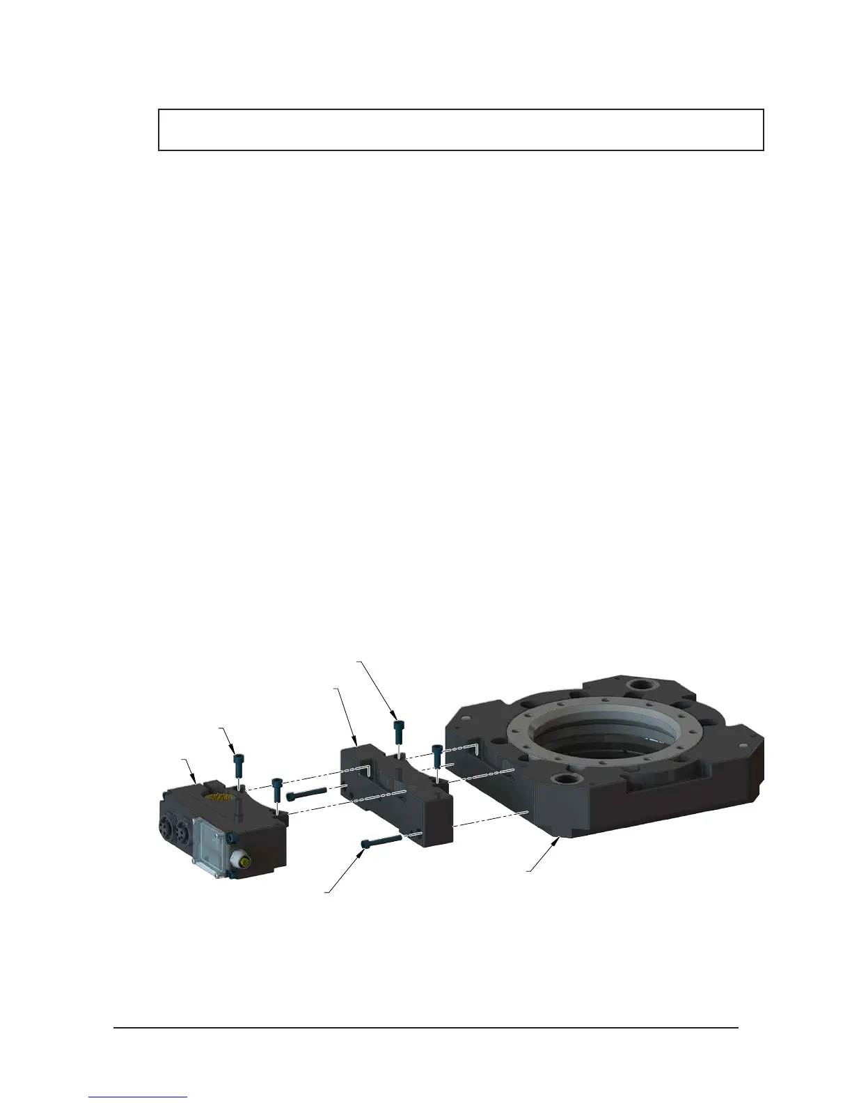
Figure 2.4—Tool Adapter Assembly Installation
Control/Signal
Tool Module
(2) M6 Socket Head
Cap Screws
(2) M5 Socket Head Cap Screws
(2) M6 Socket Head Cap Screws
(9005-20-1192) Tool Adapter Assembly
Tool Change Tool Plate
(QC-310 Shown)