Quick Change Installation and Operation Manual
Document #9620-20-E-ED15-04
Pinnacle Park • 1031 Goodworth Drive • Apex, NC 27539 USA • Tel: 919.772.0115 • Fax: 919.772.8259 • www.ati-ia.com • Email: info@ati-ia.com
E-13
8. Drawings
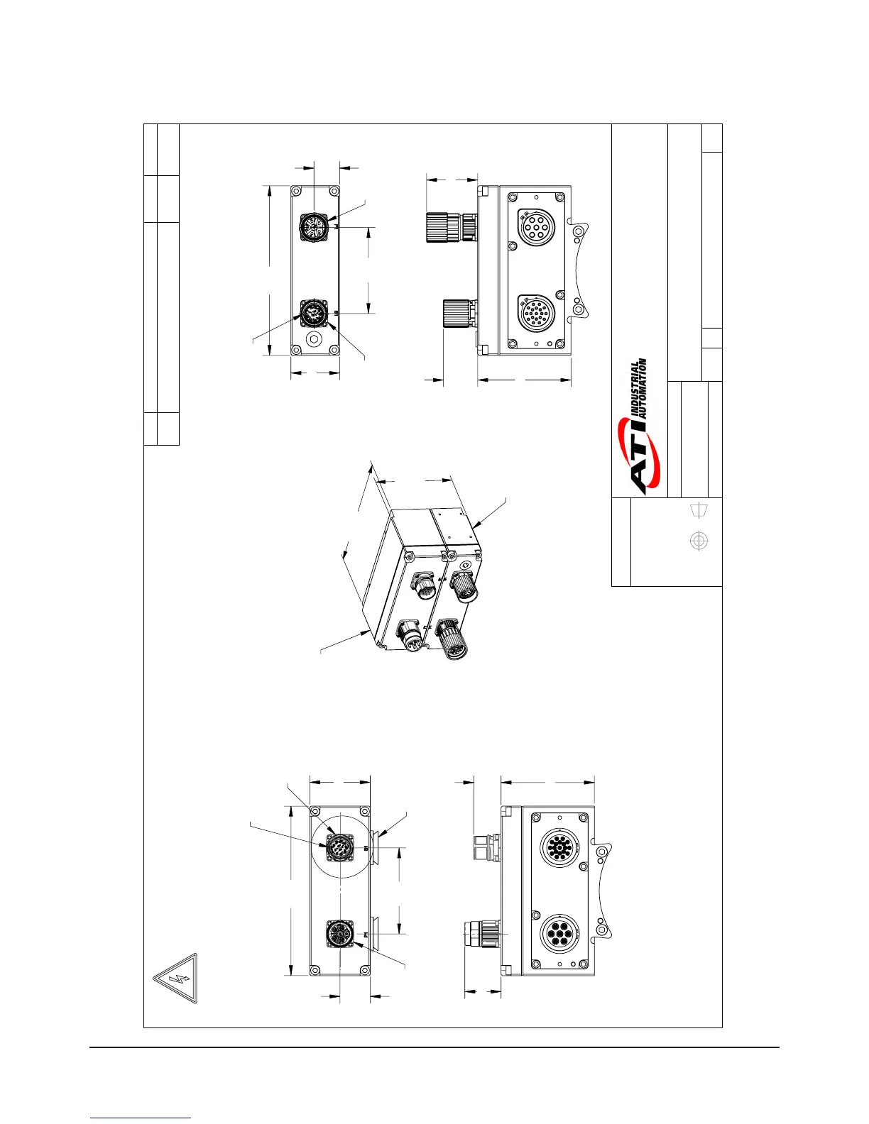
3rd ANGLE PROJECTION
102.2
Approx.
Coupled
158.8
9121-ED15-M
9121-ED15-T
87.3
25.6
33.9
56.5
80.6
28.3
158.8
Serviceable Part
(4010-0000030-01 V-Ring)
Signal
Connector
Power
Connector
Connector
Key orientation
87.3
32
47.8
80.6
24
45.6
158.8
"
DANGER!
" -
Electrical Shock Hazard
This module has a Voltage of 50V or greater, NO contact should be attempted
before removing power. This especially includes separation or insertion of the
mating connectors or any contact with the tool changer or its components.
Power
Connector
Signal
Connector
Connector
Key Orientation
9121-ED15-M
9121-ED15-T
Notes:
Module Electrical rating: Power, 13 AMPS, 630V (AC/DC) Max., Signal 3 AMPS, 160V (AC/DC) Max.
1.
Customer approval of electrical schematic is required.
2.
Customer is to approve connector selection and orientation.
3.
See sheet 4 for module wiring schematic.
4.
See Sheets 2 and 3 for Customer Interface information.
5.
Rev.
Description
Initiator
Date
05
Eco 13186; Added connection between Connector Pin 3 and
Pin Block Pin C (Internal Ground to Module Housing). Updated
Electrical Shock Hazard Note.
CF
4/6/2015
B
1:2
1
4
REVISION
NOTES: UNLESS OTHERWISE
SPECIFIED.
DO NOT SCALE DRAWING.
ALL DIMENSIONS ARE IN
MILLIMETERS.
DRAWN BY:
CHECKED BY:
P.Luczka, 4/18/14
W.Berrocal, 4/18/14
TITLE
SCALE
SIZE
DRAWING NUMBER
PROJECT #
SHEET OF
9630-20-ED15
140414-1
05
PROPERTY OF ATI INDUSTRIAL AUTOMATION, INC. NOT TO BE REPRODUCED IN ANY
MANNER EXCEPT ON ORDER OR WITH PRIOR WRITTEN AUTHORIZATION OF ATI.
1031 Goodworth Drive, Apex, NC 27539, USA
Tel: +1.919.772.0115 Email: info@ati-ia.com
Fax: +1.919.772.8259 www.ati-ia.com
ISO 9001 Registered Company
M.Hallmark, 4/25/14
ED15 Master and Tool Servo Module