Manual, Signal and Control Module, SA2 SA3
Document #9620-20-C-SA2 SA3-04
Pinnacle Park • 1031 Goodworth Drive • Apex, NC 27539 • Tel: 919.772.0115 • Fax: 919.772.8259 • www.ati-ia.com • Email: info@ati-ia.com
C-7
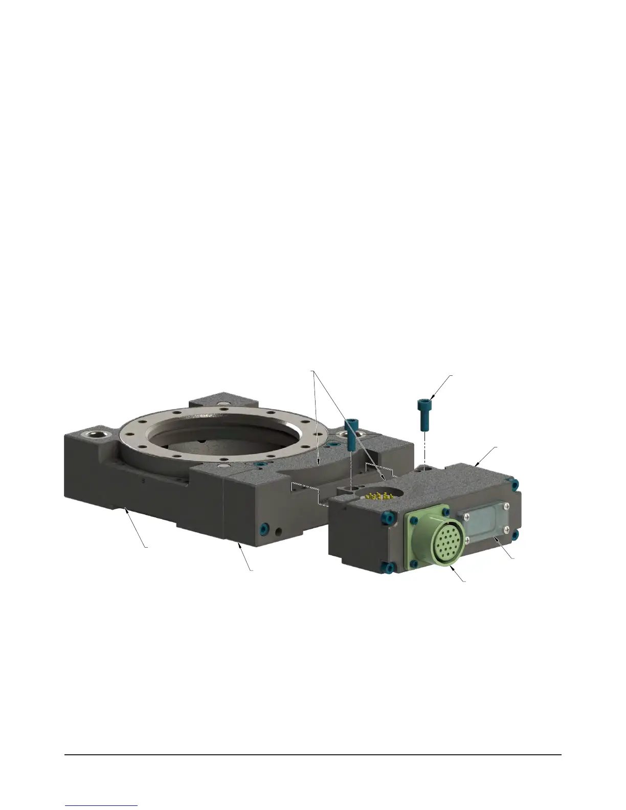
2.3 Tool Module Installation
Refer to Figure2.2 for Tool module installation instructions. Set the Tool-ID by using push button switches
on the Tool modules. Refer to Section2.5—SettingtheTool-IDontheSA3,SA4,SA5,andSA7ToolModule.
Tools required: 5 mm Allen
®
wrench(hexkey),torquewrench
Supplies required: Cleanrag,Loctite
®
242(iffastenersdonothavepre-appliedadhesive)
1. If the Tool Changer is already installed, place the tool safely in the tool stand and uncouple the Tool
Changer to allow clear access to the Master and Tool plates of the Tool Changer.
2. Turn off and de-energize all circuits (e.g. electrical, air, water, etc).
3. It may be necessary to clean the mounting surface on the air adapter prior to installing the module in
order to remove any debris that may be present.
4. Using the ledge feature as a guide, place the module onto the air adapter. Align the module with the air
adapter using the dowels in the bottom of the ledge feature.
5. If fasteners do not have pre-applied adhesive, apply Loctite 242 to the supplied M6 socket head cap
screws. Install the (2) M6 socket head screws securing the module to the air adapter using a 5 mm Allen
wrench. Tighten to 70 in-lbs (7.9 Nm).
6. Connect (e.g. power, signal, auxiliary, etc.) cables to the module. Ensure that the connectors are cleaned
prior to being secured as appropriate.
7. After installation is complete, module may be put into normal operation.
Figure 2.2—Tool Module Installation and Removal
Tool Changer
Tool Adapter
Assembly
(2) M6 Socket
Head Cap Screws
Amphenol 19-pin MS-style
Female Connector
Tool-ID
9121-SA3-T
(Shown)
Use Ledge Mounting Feature
to Properly Align Module